Variably operable oil recovery system

a technology of oil recovery system and variable operating efficiency, which is applied in the direction of gearing, piston pumps, borehole/well accessories, etc., can solve the problems of fixed (and relatively limited) operating efficiency, unattractive mechanical efficiency, and inability to disclose a variably operable oil recovery system, etc., and achieves the effect of increasing torque, increasing efficiency, and extremely high mechanical efficiency of the present invention

Inactive Publication Date: 2007-05-24
EPI ENERGY LTD A TEXAS
View PDF9 Cites 0 Cited by
  • Summary
  • Abstract
  • Description
  • Claims
  • Application Information

AI Technical Summary

Benefits of technology

[0019] Because of the make-up and configuration of the component parts of the torque variation member, an extremely efficient torque increase may be transferred in a much more compact package than traditional systems. The torque increase in a traditional system is dependent on the relative diameters and alignment of each gear within the system. Since the outer diameters (gear teeth) must mate in order to transfer torque, the envelope within which the system can be placed is quite broad. In contrast, torque increase delivered by the present invention is dependent upon the amount of eccentricity and the radius of the driver discs in relation to the position of the members which transfer torque from the driver discs to the output member. Moreover, since this entire envelope is equal to the diameter of the driver disc plus twice the eccentricity, the device of the present invention is much more compact than that of traditional oil recovery systems.
[0020] Additionally, the mechanical efficiency of the present invention is extremely high because of the near elimination of friction within the system as compared to traditional oil recovery systems. Because traditional systems depend on the engagement of turning gear teeth, a significant amount of efficiency is lost due to the “sliding” friction generated between the mating teeth. However, all torque transfer in the present system is accomplished through low-friction, rolling engagement; therefore, because the present invention completely eliminates the “sliding” friction effect of traditional systems, it is able to operate at a significantly higher efficiency than traditional oil recovery systems.
[0021] The present invention is also able to withstand much higher loading (including shock loading) than traditional oil recovery systems. In traditional systems, all loading is transferred between a single tooth of one gear mating with a single tooth of another gear; thus, at any given time all of the loading in the system is concentrated on a single gear tooth. In the present invention, loading is evenly distributed among multiple, rolling members, which, in turn, allows the system to withstand much higher loading than its traditional counterpart. Not only does this relate to a more robust system (compared to size), but it also results in a more reliable system because damage to one rolling member does not result in total system failure whereas a broken gear tooth does lead to total system failure. Therefore, the present design is much more durable and reliable than traditional oil recovery systems currently well known in the art.

Problems solved by technology

While these devices may fulfill their respective, particularly claimed objectives and requirements, the aforementioned devices and methods do not disclose a variably operable oil recovery system such as Applicant's present invention.
That is, a pump jack operates at a fixed speed, on a fixed amount of power, with a fixed stroke length, and with fixed (and relatively limited) operating efficiency.
A typical surface recovery unit, such as a “Pumpjack,” is mechanically inefficient and unattractive.
Such units rely on gears and sliding parts, which are subject to tremendous strain and friction, are large and awkward, and are of an environmentally unfriendly nature.
Commonly, underground fluid recovery systems are hindered by mechanically inefficient operation.
These inefficiencies are primarily a result of sliding part friction among components and resulting wear and tear of those components.
Perhaps the single greatest source of efficiency loss is the standard gearbox used in combination with a Pumpjack.
As a result of this configuration, gearboxes associated with standard Pumpjack operation are subject to tremendous stress.
Eventually, these stresses wear down the gears within the gearbox.
Once these gears wear down, a system breakdown is not far behind.
Another glaring problem associated with typical surface recovery devices is their relatively large and unavoidably cumbersome arrangement.
Even the smallest pumpjacks assume a relatively large footprint, and these recovery devices are unsightly and environmentally unfriendly.
During operation, their moving parts are hazardous to anyone performing repairs or simply coming within their proximity.
As a result of typical surface pumps being loud, cumbersome, visually offensive, dangerous, and environmentally unfriendly, restrictions are placed on both where and when these systems can be used.
Prohibitive zoning restrictions are often based on the way the pumps look, how they sound, and the inconvenience they cause to people in their proximity.
Further, it is widely known to those skilled in the art that conventional surface pumps are prone to leaking oil and hazardous fumes.
As such, environmental concerns are very high and periodic maintenance is required, all the while, cost of operation increases while efficiency decreases.
Surface pumps are also dangerous; all to often injury or even death results from the operation of such pumps.
These casualties often involve children who make their way to the pumps, drawn by curiosity, only to get caught in the moving parts.

Method used


Image

  • Variably operable oil recovery system
  • Variably operable oil recovery system
  • Variably operable oil recovery system

Examples


Embodiment Construction

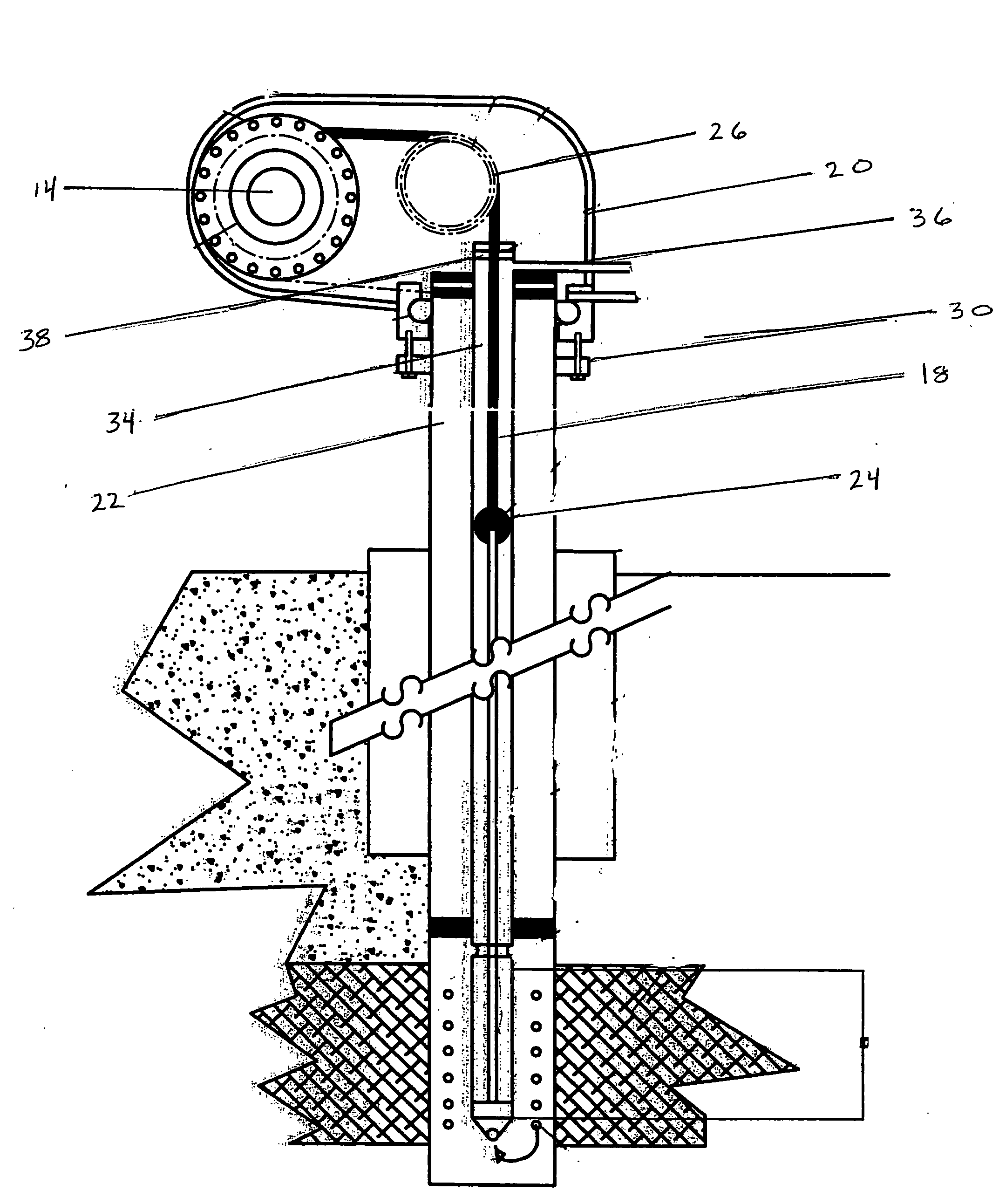
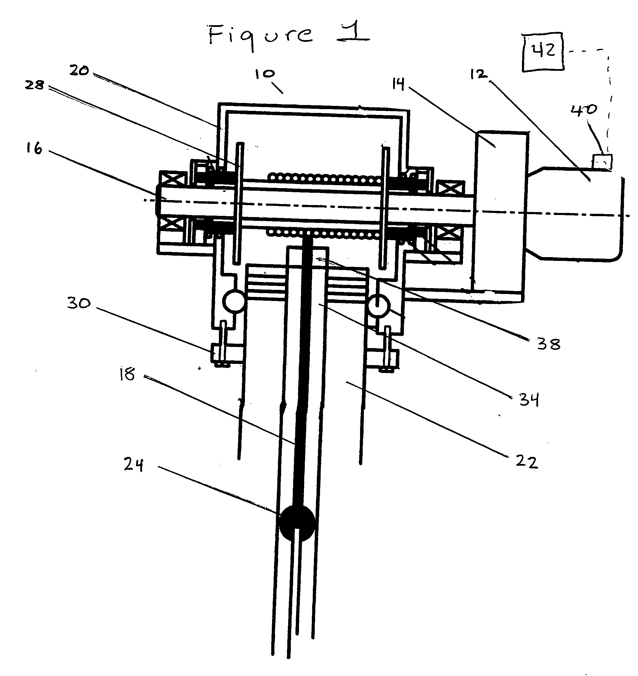
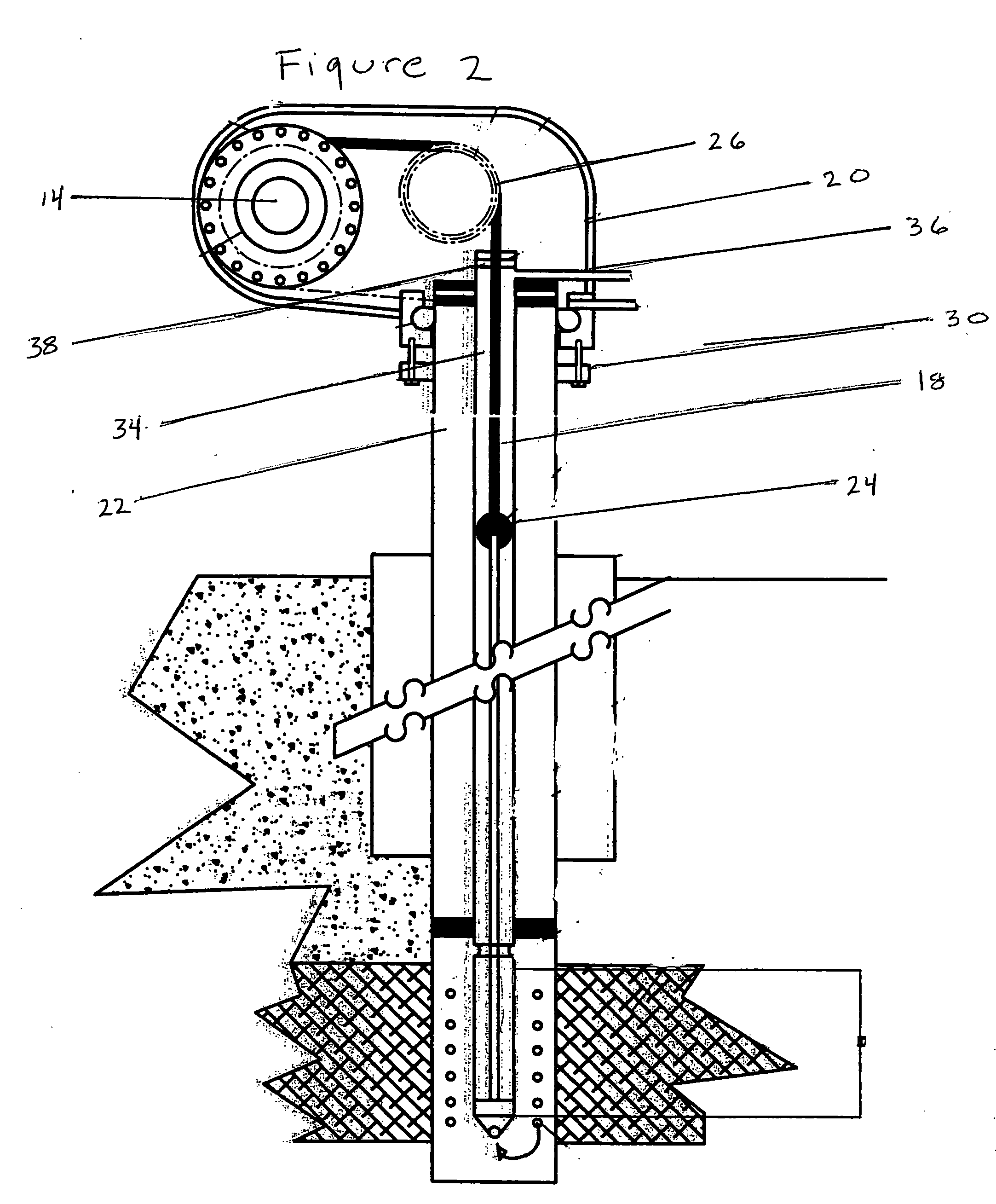
[0028] Referring to FIG. 1, the system of the present invention is generally designated by the reference numeral 10. System 10 is thought to be most beneficial in the context of oil recovery, and as will be further discussed, is thought to be particularly beneficial for such in view of its advantages with respect to smaller size, mechanical efficiency, outstanding gear reduction and torque variation characteristics, and the ability withstand sheer or shock loads—all of which result from its novel configuration.

[0029] System 10 is characterized by drive member 12 in combination with torque variation member 14. In the preferred embodiment, drive member 12 is an electronically controlled member capable of variable operation. More specifically, drive member 12 may operate at different speeds and in different modes (i.e., forward mode and reverse mode). A variety of drive members may be sufficient, if not useful, in the present system. However, in the preferred embodiment, drive member ...


PUM


Abstract

A variably operable oil recovery system having a variable motor and reducer in mechanical communication with one another where each shares a common axis of rotation. The reducer receives the drive on a high side where each has the same rotational speed, and the reducer maintains a spooled cable on its low side, which rotates at reduced speed and increased torque. The drive and reducer combination move between a first (forward) mode and a second (reverse) mode to alternatingly release and wind a spooled cable extending between the reducer low side and a below surface reciprocating pump. The system is further characterized by an electronic component combination that can continuously manage operational parameters such as stroke length, stroke speed, and power consumption.

Description

BACKGROUND OF THE INVENTION [0001] 1. Field of the Invention [0002] The present invention generally relates to an oil recovery system. More specifically, the present invention relates to an oil recovery system where a below surface reciprocating pump is actuated by a variably operable motor and reducer combination alternating between a first and second mode. [0003] 2. Background Information [0004] No doubt there have been countless devices and methods developed over the years for improving the efficiency of oil recovery. While these devices may fulfill their respective, particularly claimed objectives and requirements, the aforementioned devices and methods do not disclose a variably operable oil recovery system such as Applicant's present invention. Indeed, it is well known to those skilled in the art that the oil recovery industry is filled with an endless variety of devices and methods all having a common objective—the improved recovery of oil. [0005] Nevertheless, known oil reco...

Claims


Application Information

Patent Timeline
Patent Type & Authority Applications(United States)
IPC IPC(8): F04B39/00
CPCF04B47/02
Inventor JONES, DANCLARK, DEVANE
Owner EPI ENERGY LTD A TEXAS
Why Eureka
Try Eureka