Turbocharged engine system and method of operation

a turbocharged engine and engine technology, applied in the field of engine systems, can solve the problems of difficult substantial impact on the specific fuel consumption (sfc) and particulate matter emissions, and inability to provide efficient control of the exhaust gas circulation

Active Publication Date: 2007-05-31
GE GLOBAL SOURCING LLC
View PDF37 Cites 55 Cited by
  • Summary
  • Abstract
  • Description
  • Claims
  • Application Information

AI Technical Summary

Benefits of technology

[0005] In accordance with certain embodiments, the present technique has a system. The system includes an internal combustion engine having an intake manifold and an exhaust manifold. The system also includes a high pressure turbocharger having a variable geometry high pressure turbine drivingly coupled to a high pressure compressor, wherein the variable geometry high pressure turbine is driven by a first portion of exhaust gases from the exhaust manifold, wherein the high pressure compressor is configured to compress an intake air and to provide the compressed intake air to the intake manifold. The system also includes a low pressure turbocharger having a variable geometry low pressure turbine drivingly coupled to a low pressure compressor, wherein the variable geometry low pressure turbine is driven by a second portion of the exhaust gases from the exhaust manifold, wherein the low pressure compressor is configured to compress a third portion of the exhaust gases from the exhaust manifold and to provide the compressed third portion to the intake manifold, wherein the first and second portions of the exhaust gases are different from one another.
[0006] In accordance with certain embodiments, the present technique has a method of operating an engine system. The method includes routing a first portion of exhaust gases from an internal combustion engine to drive a variable geometry high pressure turbine of a high pressure turbocharger and routing a second portion of the exhaust gases to drive a variable geometry low pressure turbine of a low pressure turbocharger. The method also includes routing a third portion of the exhaust gases to a low pressure compressor of the low pressure turbocharger to compress the third portion of exhaust gases for intake into the internal combustion engine, wherein the first and second portions of exhaust gases are different from one another.

Problems solved by technology

Unfortunately, it is difficult to control the exhaust gas recirculation of the exhaust gases while substantially overcoming the pressure difference between the intake and exhaust manifolds.
Further, such techniques substantially impact the specific fuel consumption (SFC) and particulate matter (PM) emissions and do not provide efficient control of the exhaust gas circulation for the entire range of throttle notch settings applied to the duty cycle for locomotive operation and at high altitudes.

Method used


Image

  • Turbocharged engine system and method of operation
  • Turbocharged engine system and method of operation
  • Turbocharged engine system and method of operation

Examples


Embodiment Construction

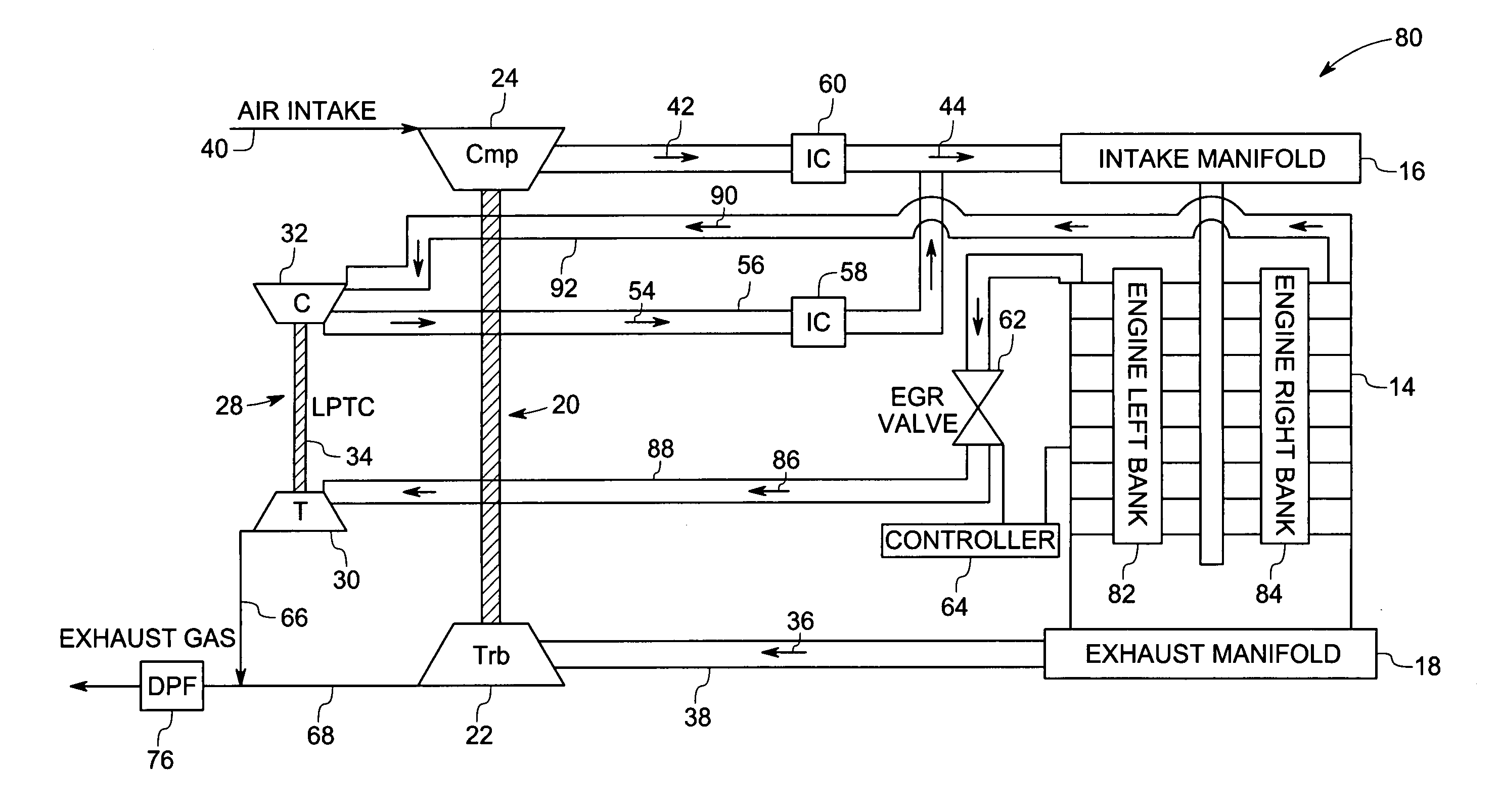
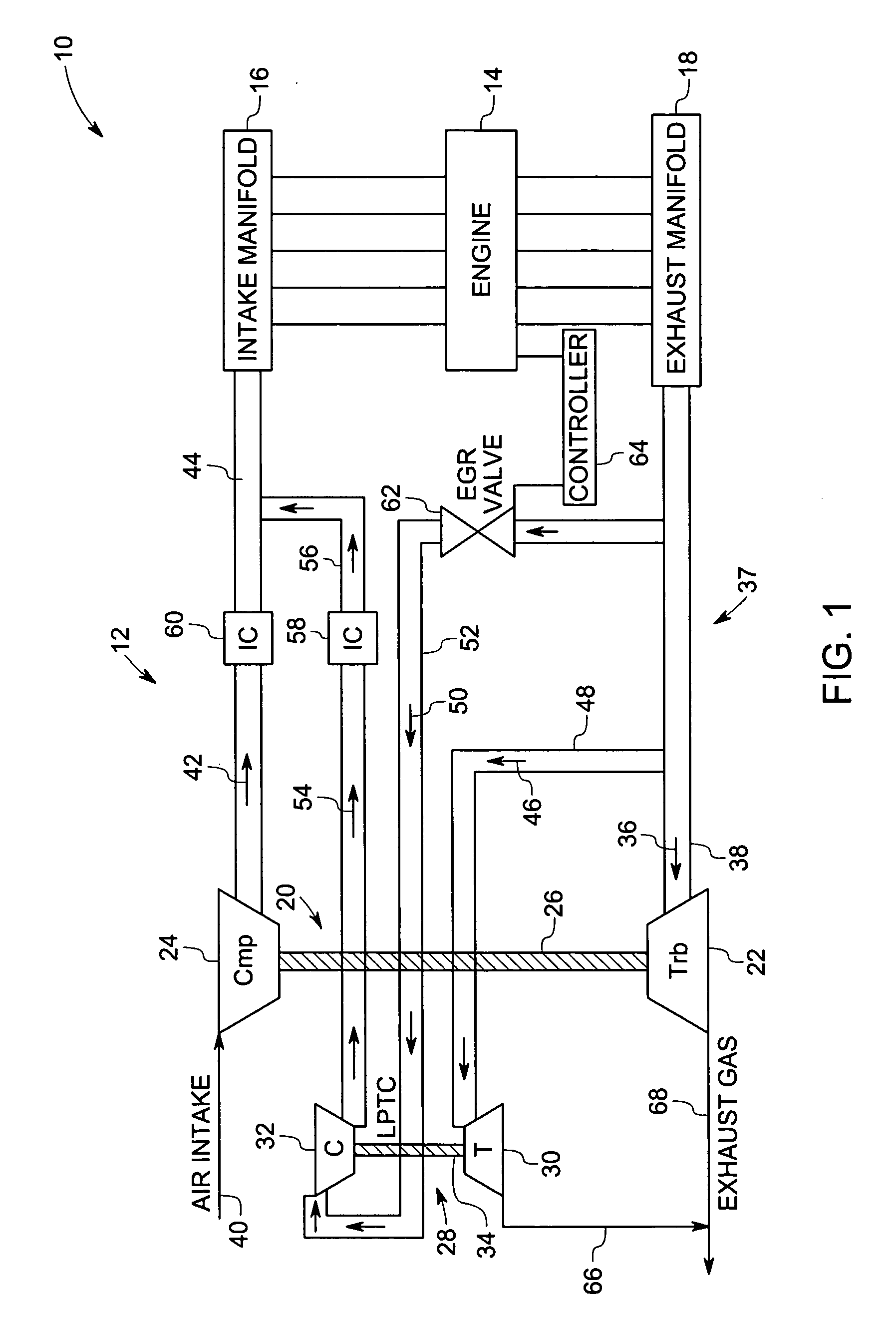
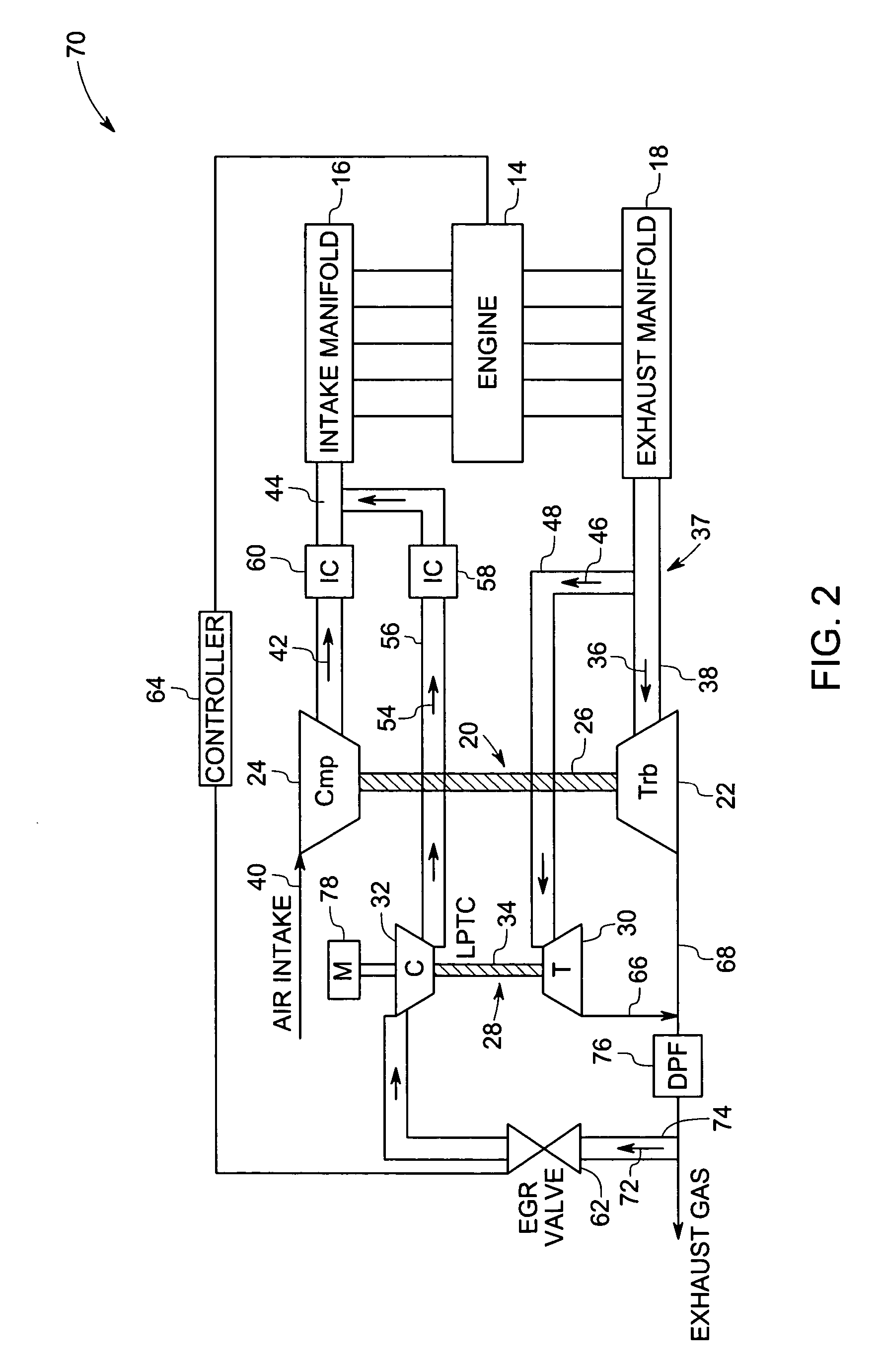
[0017] As discussed in detail below, embodiments of the present technique function to reduce emissions in turbocharged internal combustion engine systems such as employed in locomotives and vehicles. For example, the internal combustion engines may include spark ignition engines or compression-ignition engines, such as diesel engines. In particular, the present technique includes employing selective exhaust gas recirculation with the intake air within the turbocharged internal combustion engine system to minimize emissions, such as NOx emissions, from the system. In particular, the mixing of the exhaust gases with the intake air lowers the peak combustion temperature and the adiabatic flame temperature, thereby reducing the emissions from the system.

[0018] Turning now to the drawings and referring first to FIG. 1, a turbocharged internal combustion engine system 10 having an exemplary exhaust gas recirculation mechanism 12 is illustrated. Examples of the turbocharged internal engin...


PUM


Abstract

A system is provided. The system includes an internal combustion engine having an intake manifold and an exhaust manifold. The system also includes a high pressure turbocharger having a variable geometry high pressure turbine drivingly coupled to a high pressure compressor, wherein the variable geometry high pressure turbine is driven by a first portion of exhaust gases from the exhaust manifold, wherein the high pressure compressor is configured to compress an intake air and to provide the compressed intake air to the intake manifold. The system also includes a low pressure turbocharger having a variable geometry low pressure turbine drivingly coupled to a low pressure compressor, wherein the variable geometry low pressure turbine is driven by a second portion of the exhaust gases from the exhaust manifold, wherein the low pressure compressor is configured to compress a third portion of the exhaust gases from the exhaust manifold and to provide the compressed third portion to the intake manifold, wherein the first and second portions of the exhaust gases are different from one another.

Description

BACKGROUND [0001] The invention relates generally to engine systems and more particularly to a technique for reducing pollutant emissions, e.g., Nitrogen Oxide (NOx) emissions, in turbocharged internal combustion engines. [0002] Various types of internal combustion engines are in use for powering vehicles such as locomotives, passenger cars and other equipment. An internal combustion engine may include one or more turbochargers for compressing an intake charge (e.g., atmospheric air), which is supplied to one or more combustion chambers within the engine. Each turbocharger includes a turbine driven by exhaust gases from the engine and a compressor driven by the turbine. Moreover, the compressor receives the atmospheric air to be compressed and provides the compressed air to the combustion chambers. [0003] Typically, a turbocharged internal combustion engine is operated such that the intake manifold pressure is higher than the exhaust manifold pressure in the engine. In certain tradi...

Claims


Application Information

Patent Timeline
Patent Type & Authority Applications(United States)
IPC IPC(8): F01N5/04F01N3/00F02D23/00
CPCF01N3/021F02B37/007F02B37/16F02B37/24F02M25/0711F02M25/0727F02M25/0739F02M25/0748Y02T10/121Y02T10/144Y02T10/20F02M26/08F02M26/23F02M26/34F02M26/42Y02T10/12
Inventor BOYAPATI, CHENNA KRISHNA RAOVAIDYANATHAN, KRISHNAMURTHY
Owner GE GLOBAL SOURCING LLC
Why Eureka
Try Eureka