Welding torch with a torch housing and drive for welding rod transport

Active Publication Date: 2007-05-31
FRONIUS INTERNATIONAL GMBH
View PDF11 Cites 23 Cited by
  • Summary
  • Abstract
  • Description
  • Claims
  • Application Information

AI Technical Summary

Benefits of technology

[0007] The object of the present invention, therefore, resides in providing a welding torch or wire feed unit, respectively, of as small a structural size as possibl

Problems solved by technology

Hence, there are no more transition surfaces on which heat can

Method used


Image

  • Welding torch with a torch housing and drive for welding rod transport
  • Welding torch with a torch housing and drive for welding rod transport
  • Welding torch with a torch housing and drive for welding rod transport

Examples


Example

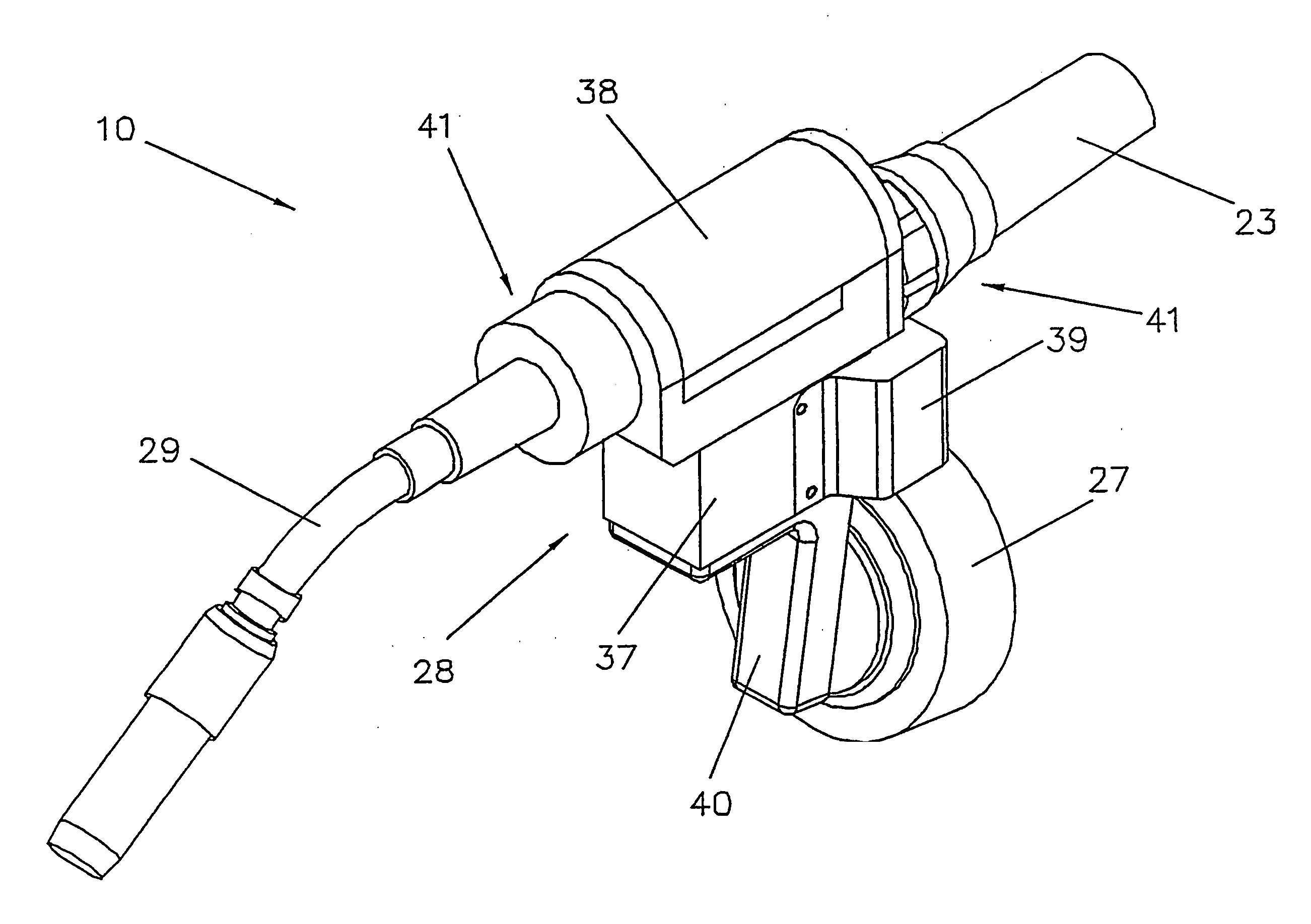
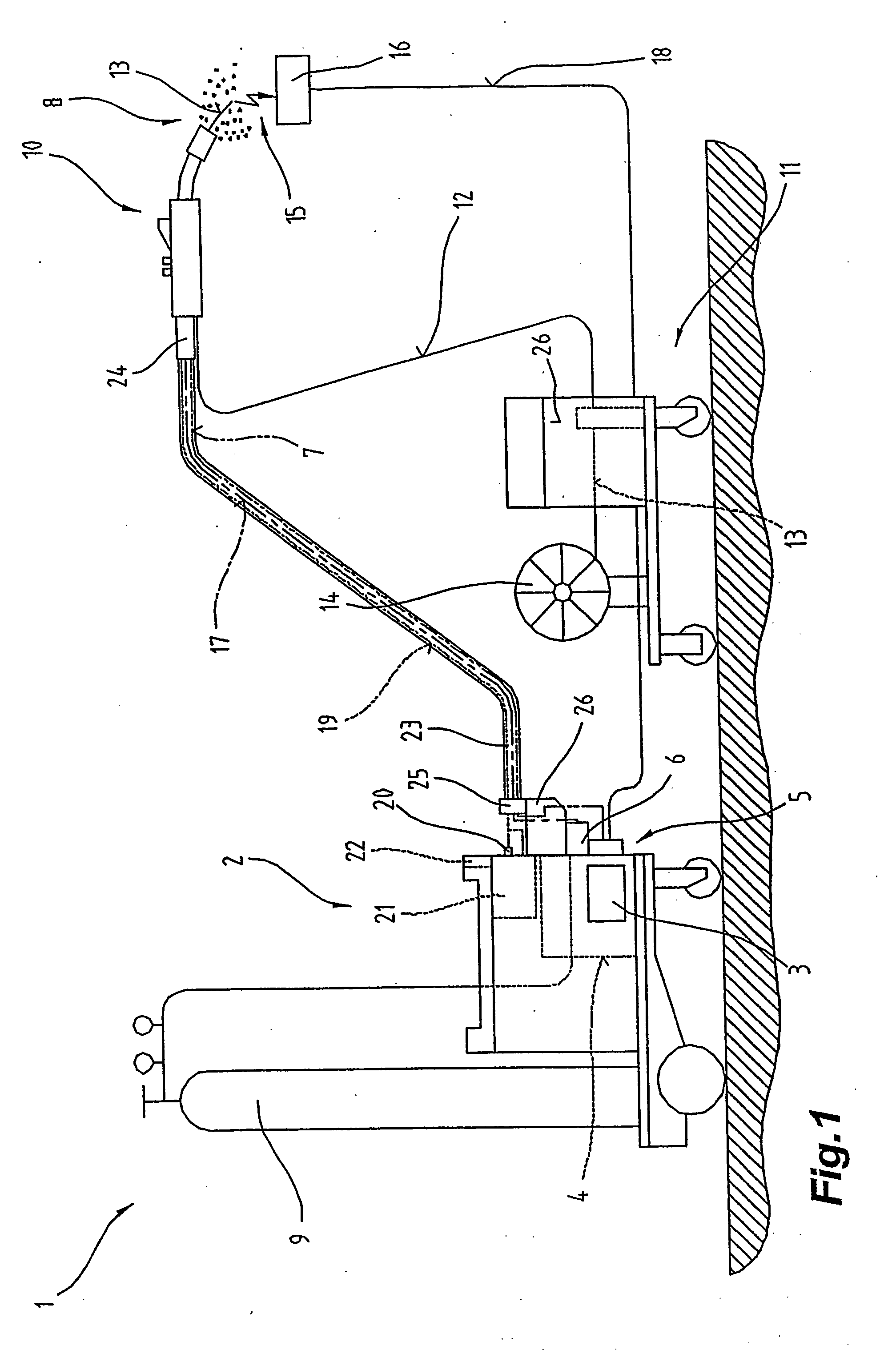
[0061]FIG. 1 depicts a welding apparatus 1, or welding system, for various processes or methods such as, e.g., MIG / MAG welding or WIG / TIG welding, or electrode welding methods, doublewire / tandem welding methods, plasma or soldering methods etc.

[0062] The welding apparatus 1 comprises a power source 2 including a power element 3, a control device 4, and a switch member 5 associated with the power element 3 and control device 4, respectively. The switch member 5 and the control device 4 are connected to a control valve 6 arranged in a feed line 7 for a gas 8, in particular a protective gas such as, for instance, carbon dioxide, helium or argon and the like, between a gas reservoir 9 and a welding torch 10 or torch.

[0063] In addition, a wire feeder 11, which is usually employed in MIG / MAG welding, can be controlled by the control device 4, whereby a filler material or welding wire 13 is fed from a feed drum 14 or wire coil into the region of the welding torch 10 via a feed line 12. I...


PUM

PropertyMeasurementUnit
Electrical conductivityaaaaaaaaaa
Electrical conductoraaaaaaaaaa
Electric propertiesaaaaaaaaaa

Abstract

In a welding torch including a torch housing (28) and, preferably, a tube bend (29) capable of being fastened thereto, wherein a drive unit (30) for feeding a welding wire (13) is arranged in the torch housing (29) and the drive unit (30) is formed by at least one pair of rollers, in particular a drive roller (31) and a pressure roller (32), as well as a drive motor, a part of the torch housing (28) is designed as a component of the drive unit (30). A rotor (45), in particular a motor shaft (46), of the drive motor (33) is fastened to the torch housing (28) via a bearing, in particular via bearings (43, 44), to stabilize and position the rotor (45). In a welding wire feed drive motor including bearings (43, 44), a rotor (45), in particular a motor shaft (46) and a rotor winding (49) or rotor magnets, and a stator pack, in particular stator winding (47) or stator magnets, at least a part of the motor shaft (46), in particular the retention zone of a drive roller (31), is electrically insulated from the housing, in particular stator housing (65) or base body (37).

Description

BACKGROUND OF THE INVENTION [0001] 1. Field of the Invention [0002] The invention relates to a welding torch including a torch housing and, preferably, a tube bend capable of being fastened thereto, wherein a drive unit for feeding a welding wire is arranged in the torch housing and the drive unit is formed by at least one pair of rollers, in particular a drive roller and a pressure roller, as well as a drive motor. [0003] 2. Prior Art [0004] From the prior art, it is known that drive motors used in welding torches are designed as independent assemblies. In those cases, the drive motor has its own stator house, which carries or incorporates all elements like the stator windings or stator magnets, the rotor with the stator pack, in particular rotor windings or rotor magnets, the bearings for the rotor, the end shield and a motor plate. That independent drive motor assembly is fastened to the torch housing. In order to increase the feeding power, a gearbox is fastened to the motor sha...

Claims


Application Information

Patent Timeline
IPC IPC(8): B23K9/12B23K9/133
CPCB23K9/1336H02K5/08B23K9/133H02K7/083H02K7/14H02K7/003
Inventor FLATTINGER, GUNTHERSCHORGHUBER, MANFREDHIMMELBAUER, KARIN
Owner FRONIUS INTERNATIONAL GMBH
Why Eureka
Try Eureka