Eureka AIR delivers breakthrough ideas for toughest innovation challenges, trusted by R&D personnel around the world.

Volumetric displacement dispenser

Inactive Publication Date: 2007-05-31
EHRET VINCENT +2
View PDF13 Cites 40 Cited by
  • Summary
  • Abstract
  • Description
  • Claims
  • Application Information

AI Technical Summary

Benefits of technology

[0012] It is accordingly an aspect of this invention to provide an invented device and method that provides a means to preserve the quality and bouquet of a wine and prevent further aging of the wine by minimizing introduction of air into the wine container and causing an occupation of the void space within the container by an expandable displacement dispenser that serves to protect the contained wine from contact with the ambient atmosphere.
[0013] It is accordingly another aspect of this invention to provide a wine preservation and dispensing system for bottled wine to allow wine to be dispensed from the bottle by the glass while protecting the wine in the bottle from the harmful effects of being exposed to the ambient air.

Problems solved by technology

An effective means for preserving wines and other beverages, once they have been initially decanted, has long been a problematic issue that has confronted the consumer of these commodities.
Due to the chemical composition of wine, it is especially susceptible to degradation via oxidation processes that pose the risk of spoiling the flavor and bouquet in the short term and converting it to a less desirable product, i.e., vinegar, in the long term.
In each of these methods, the container contained excess air and did not preserve the quality of the wine.
However, without removal of air in the void space above the wine's surface, the wine was still subject to degradation.
But each volume displacement method introduced new contaminants, (dirt, oil, bacteria, etc.) to the wine, which impaired the quality of the stored wine.
Also, volume replacement by stones, glass or other solid media increased weight of the container, creating transportation problems.
This method moreover served to negatively impact taste and body of the wine as bacteria and contaminants, which reacted with the wine, were introduced to the wine by the volume replacement objects.
Another problem was that trace amounts of the oil were incorporated into the wine causing an oily taste and sometimes affecting the bouquet.
But, issues with decanting and contaminants still persisted.
This approach is both expensive and cumbersome to use, as the individual user expends additional effort in installing the dispenser on an uncorked bottle of wine.
This can be a potential risk for the individual user, as the cork may be suddenly expelled and the contents discharged.
This system though effective does not readily lend itself to those occasions when a consumer entertains a small party and it would be desirable to decant the wine by hand from the container.
Although this patent teaches decanting the liquid within the bag through a decrease in volume obtained through external force, this patent does not address the problem of air entrance into the previously decanted liquid container.
However, the insertion of the hollow needle through the bottle cork can introduce air into the void space above the wine level and cause deterioration of the contained wine.
'680 teaches, as most beverages and wines are stored in glass containers, the amount of pressure that can be applied to the container is limited.
However, the success of this system has been variable, as a number of physical parameters limit the effectiveness of this technique.
As these devices rely on the penetration of the stopper, even given the compressive qualities of corks, rubber and other materials used as stoppers, it is difficult to maintain a required vacuum for any length of time.
Another shortcoming of this approach is the failure to foresee the trend of winemakers away from cork and toward plastic lined metal screw caps, which will not work with these systems.

Method used


Image

  • Volumetric displacement dispenser
  • Volumetric displacement dispenser
  • Volumetric displacement dispenser

Examples


Embodiment Construction

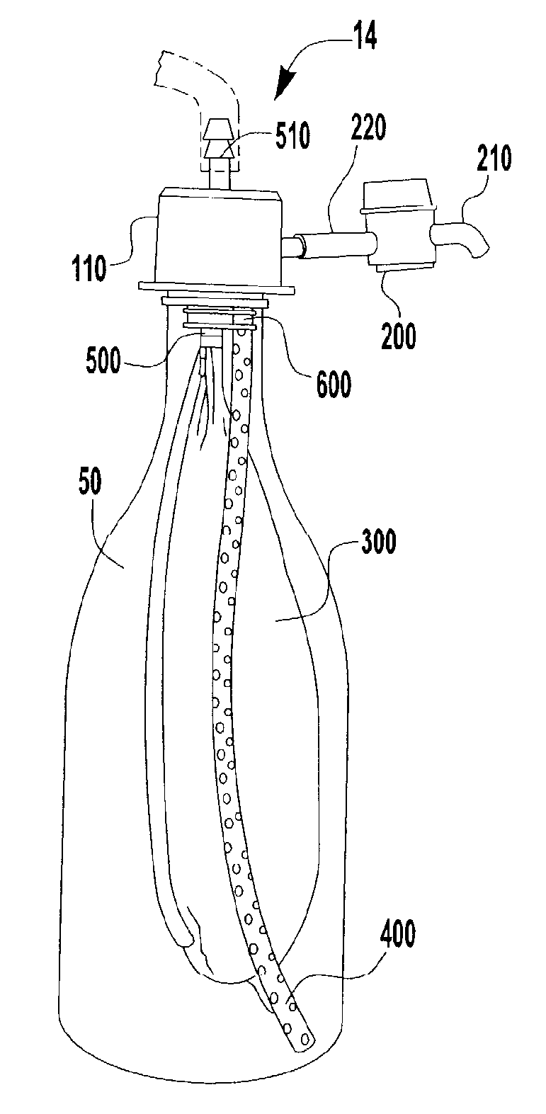
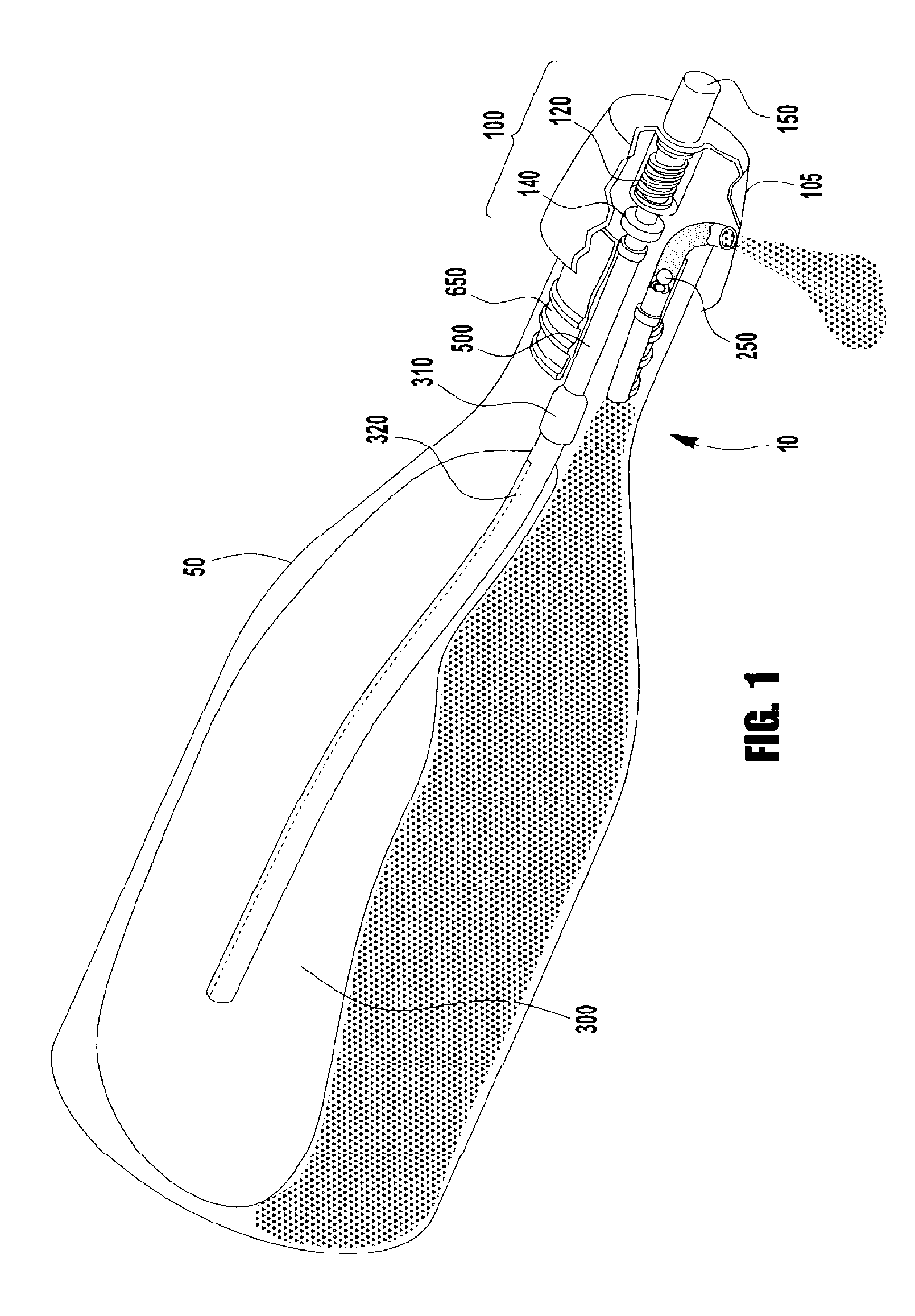
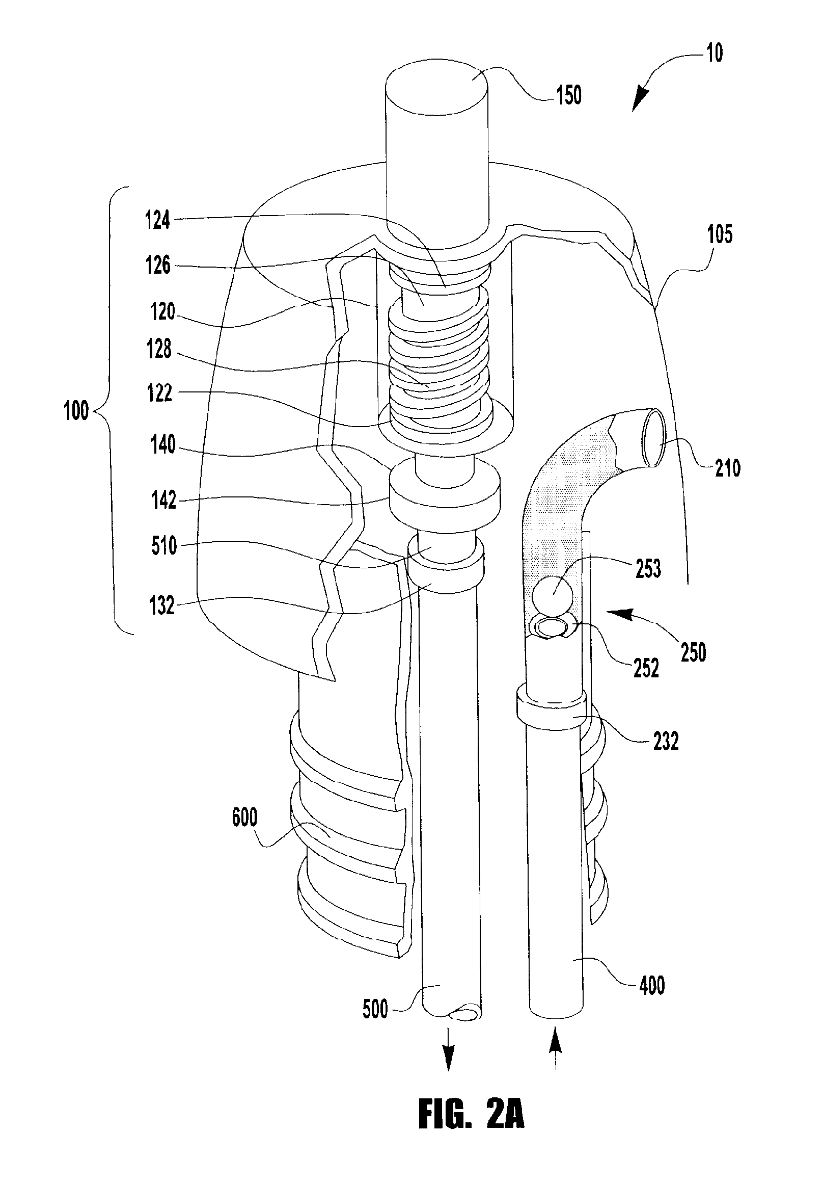
[0047] Referring to FIGS. 1-5, the Figures illustrate several embodiments of the volumetric displacement dispenser device comprising a flexible inflatable operative balloon and means permitting liquids and gases to flow only in one direction.

[0048] Referring to FIGS. 1 and 2A, volumetric displacement dispenser 10 is illustrated as inserted in a bottle 50 by ported stopper 600 wherein components of said dispenser 10 comprise a cap assembly 100. Cap assembly 100 comprises cap-air pump 105 with one aperture on the top surface for air pump piston shaft 150 and further comprises air pump / air vent assembly 120 connected to air / gas pressure tube 500 with air / gas check valve 140 inserted therein. Cap assembly 100 further comprises a liquid discharge tube 400 wherein liquid check valve 250 is inserted therein. Volumetric displacement device casing 320 is retained by retaining clip 310 on air / gas pressure tube 500. Volumetric displacement operative balloon 300 is also connected to air / gas pr...


PUM


Abstract

A volumetric displacement dispenser and method of using the dispenser is disclosed for dispensing liquid contents from an interior of a bottle with a bottle neck while preventing air from filling a void created within the interior of the bottle caused by the liquid contents being poured out of the bottle by gravity. The dispenser includes a stopper having first and second boreholes extending there through, the stopper being adapted to form an air-tight seal when it is seated into the bottle neck. An air pressure tube routed through the first of the boreholes has a first end open to atmospheric air and a second end open to the interior of the bottle. An expandable volumetric displacement balloon is attached to the second end of the air pressure tube and a one-way liquid valve is disposed in the outlet of the liquid flow channel in the stopper.

Description

CROSS REFERENCE TO RELATED APPLICATIONS [0001] This application is a continuation in part of copending U.S. application Ser. No. 11 / 332,277 entitled VOLUMETRIC DISPLACEMENT DISPENSER, and filed on Jan. 13, 2006, which in turn claims the benefit of U.S. Provisional Patent Application Ser. No. 60 / 647,610, filed on Jan. 27, 2005.FIELD OF THE INVENTION [0002] The present invention specifically relates to a volumetric displacement dispenser to provide the individual user the capability of dispensing a given quantity of dispensable liquids or other beverages, such as wines or other perishable commodities, from a container and allowing the storage of the beverage over an extended period of time through the exclusion of air from the container; thus reducing degradation of the container contents whereby the desirable characteristics of the beverage are preserved in their original state. In one embodiment, the volumetric displacement dispenser comprises an air pump, check valves and an expand...

Claims


Application Information

Patent Timeline
IPC IPC(8): B67D5/42B65D83/00B67D5/60B67D7/60B67D7/78
CPCB67D1/045
Inventor EHRET, VINCENTEATON, EDWARDMARCHESE, THOMAS
Owner EHRET VINCENT
Why Eureka
Eureka Blog
Learn More