Marginal check voltage setting means built-in power-supply device

a technology of marginal check voltage and setting circuit, which is applied in the direction of power conversion systems, dc-dc conversion, instruments, etc., can solve the problems of information processing equipment in a state of error, difficult to set a desired value for marginal check voltage, and difficulty in downsizing and adopting ics, so as to prevent any discordance and reduce the size and adoption of integrated circuits

Inactive Publication Date: 2007-05-31
HITACHI LTD
View PDF10 Cites 13 Cited by
  • Summary
  • Abstract
  • Description
  • Claims
  • Application Information

AI Technical Summary

Benefits of technology

[0015] The present invention provides the power-supply device with a built-in marginal check voltage setting circuit which is suitable for downsizing and adoption of integrated circuits. Further, implementation of the present invention will prevent any discordance that otherwise may happen between the marginal check voltage and the over-voltage detection reference voltage or the power-good reference voltage.

Problems solved by technology

In order to perform voltage marginal check, the prior art power-supply device requires insertion of a voltage marginal check power-supply device, and this makes downsizing and adoption of ICs difficult.
Also, it is difficult to set a desired value for the marginal check voltage.
What is regarded a problem in the voltage marginal check as a part of quality assurance testing procedure for the information processing equipment is the relationship between power-good and over-voltage detection.
If the marginal check voltage exceeds the range of power-good voltage, the information processing equipment gets in a state of error and becomes unable to exercise the voltage marginal check.

Method used


Image

  • Marginal check voltage setting means built-in power-supply device
  • Marginal check voltage setting means built-in power-supply device
  • Marginal check voltage setting means built-in power-supply device

Examples


Embodiment Construction

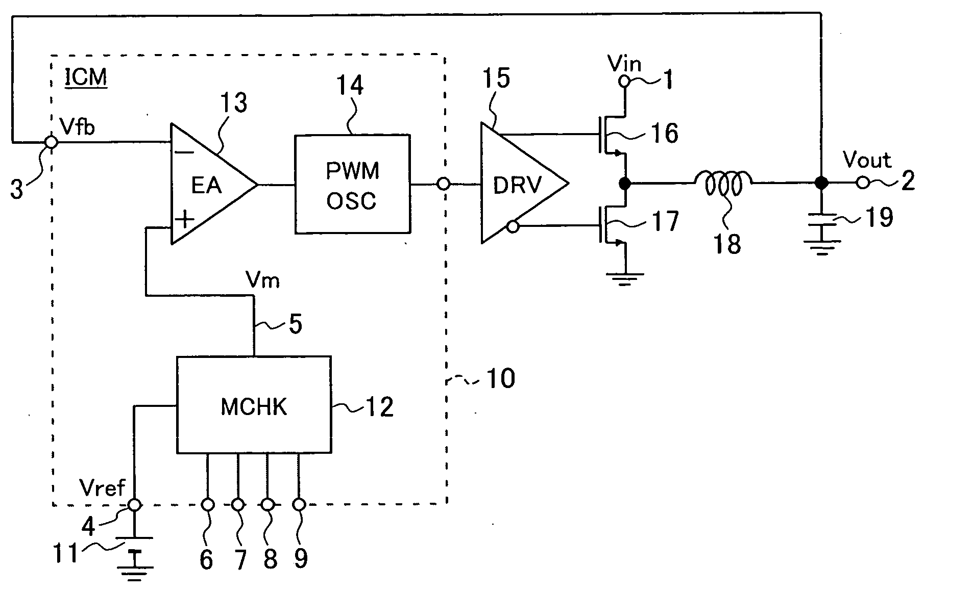
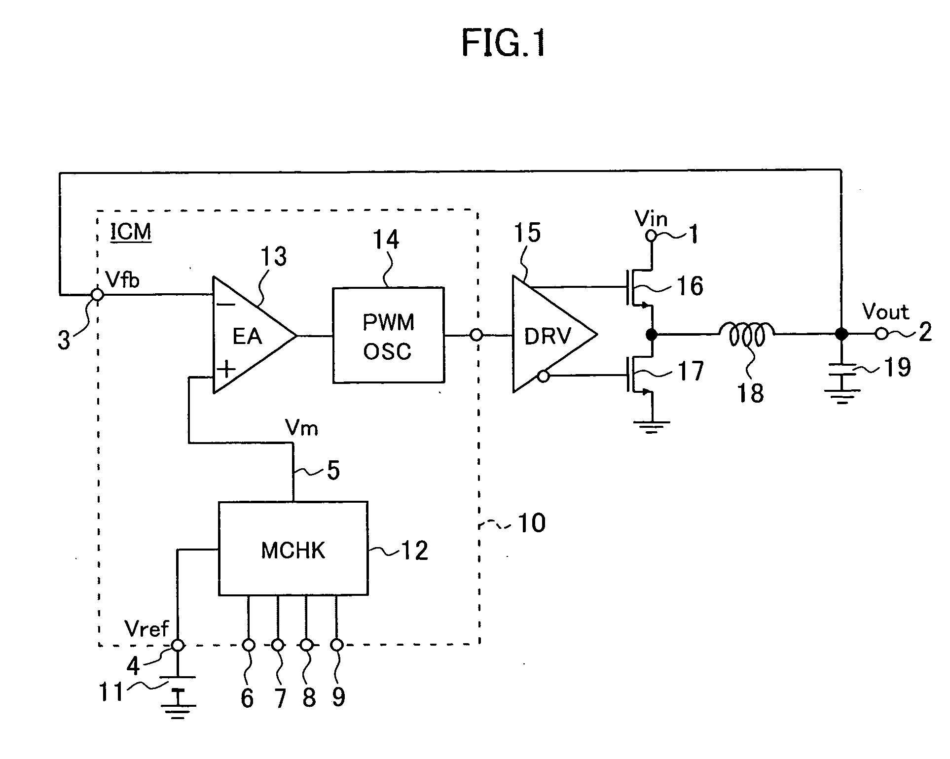
[0027]FIG. 1 shows one embodiment of the power-supply device according to the present invention. The power-supply device in this embodiment comprises a marginal check voltage setting circuit 12, an error amplifier 13, a pulse width modulation oscillator 14, a driver 15, a pair of power MOSFET 16 and 17, an inductor 18, and a capacitor 19. An LC smoothing filter is formed by the inductor 18 and the capacitor 19.

[0028] The drain of the upper-side power MOSFET 16 is connected to the input terminal 1 of the power-supply device, and the source of the lower-side MOSFET 17 is earthed. The joint point between the drain of the upper-side power MOSFET 16 and the source of the lower-side MOSFET 17 is connected to the output terminal 2 of the power-supply device via the LC smoothing filter. The output voltage Vout at the output terminal 2 is fed back to the feedback voltage terminal 3 as the feedback voltage Vfb (=Vout).

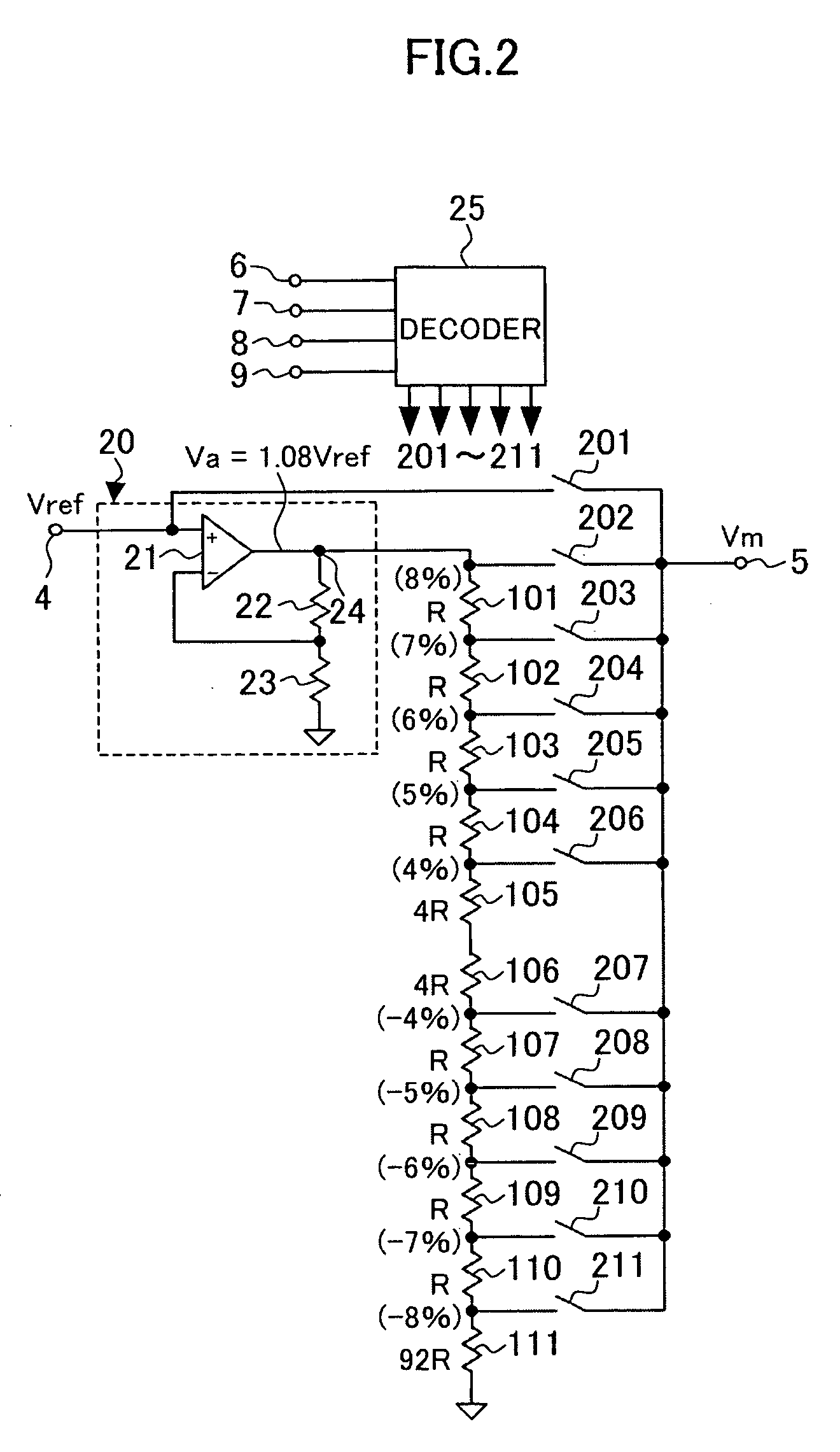
[0029] First of all, the case where the power-supply device in this embod...


PUM


Abstract

A power-supply device comprising such marginal check voltage setting circuit that is easily adaptable to downsizing of the device and to configuration using ICs. The power-supply device of this invention comprises a marginal check voltage setting circuit that accepts input of a reference voltage and sets a desired marginal check voltage, an error amplifier that accepts input of the marginal check voltage and also the output voltage of the power-supply device and delivers output of an error signal, that is, the difference between the two inputs, a pulse width modulation oscillator that modulates the pulse width of the output from the error amplifier, a driver circuit that generates driving signal from the pulse signal originating from the pulse width modulation oscillator, and a pair of power semiconductor switching devices that work to step down the input voltage and generate an output voltage based on the driving signal. Furthermore, the power-supply device is also provided with an over-voltage detection circuit that sets an over-voltage detection reference voltage, and a power-good circuit that sets a power-good determination reference voltage, both circuits being positioned at the output terminal of the marginal check voltage setting circuit.

Description

FIELD OF THE INVENTION [0001] This invention relates to a power-supply device with a built-in marginal check voltage setting circuit, and particularly to a power-supply device functioning as a step-down DC-DC converter. BACKGROUND OF THE INVENTION [0002] In the manufacturing process of information processing equipments for controlling hard disk devices and other related devices, it is customary to conduct a voltage marginal check as a part of quality assurance testing procedure. In the voltage marginal check, marginal check voltage which is obtained by varying feedback voltage from the power-supply device or the reference voltage upward and downward within a certain range is used to check if logical circuits or memories of semiconductor devices are in proper working condition. [0003] Japanese published and unexamined patent application gazette H11-352195 refers to exercising voltage marginal check for the information processing equipment that has no provision of interface for voltag...

Claims


Application Information

Patent Timeline
Patent Type & Authority Applications(United States)
IPC IPC(8): G05F1/00
CPCH02M3/156H02M2001/0025H02M1/0025
Inventor SASE, TAKASHIKANOUDA, AKIHIKOKAWAKUBO, YOSUKE
Owner HITACHI LTD
Why Eureka
Try Eureka