Electrophoretic display apparatus and driving method thereof

a technology of display apparatus and display apparatus, which is applied in the direction of static indicating device, non-linear optics, instruments, etc., can solve the problems of inability to display stable gradation, difficult control, and failure to be put into practical us

Inactive Publication Date: 2007-05-31
CANON KK
View PDF13 Cites 29 Cited by
  • Summary
  • Abstract
  • Description
  • Claims
  • Application Information

AI Technical Summary

Benefits of technology

[0027] wherein at the surface of the substrate defining the container, a resistance layer electrically connecting the first electrode and the second electrode is formed, and the electrophoretic particles in the container are moved between a surface of the partition wall and a surface of the resistance layer to effect display.

Problems solved by technology

However, most of liquid crystal materials have no memory characteristic, so that it is necessary to continuously apply a voltage to the liquid crystal during a display period.
On the other hand, a liquid crystal material having a memory function cannot readily ensure a reliability in the case of assuming its use in various environments such as outdoor environment as in the wearable PC, thus failing to be put into practical use.
For this reason, in the case where halftone is displayed, when the electrophoretic particles is partially moved on a display electrode depending on an applied voltage, a relationship between the applied voltage and halftone level is largely deviated from a linear relationship, so that it becomes difficult to effect control.
As a result, stable gradation cannot be displayed.
However, an electric field toward the central portion of the pixel G is very weak, so that the electrophoretic particles do not reach the pixel central portion, thus failing to provide a sufficient contrast.
As a result, a display memory characteristic is lost in some cases.
However, in this case, a positional deviation of the color filter from the pixel is caused to occur.
However, in the case of providing the black matrix, it is difficult to obtain a high aperture ratio.
However, the resultant structure is complicated and in addition, light absorption by the transparent electrode cannot be negligible.

Method used


Image

  • Electrophoretic display apparatus and driving method thereof
  • Electrophoretic display apparatus and driving method thereof
  • Electrophoretic display apparatus and driving method thereof

Examples


first embodiment

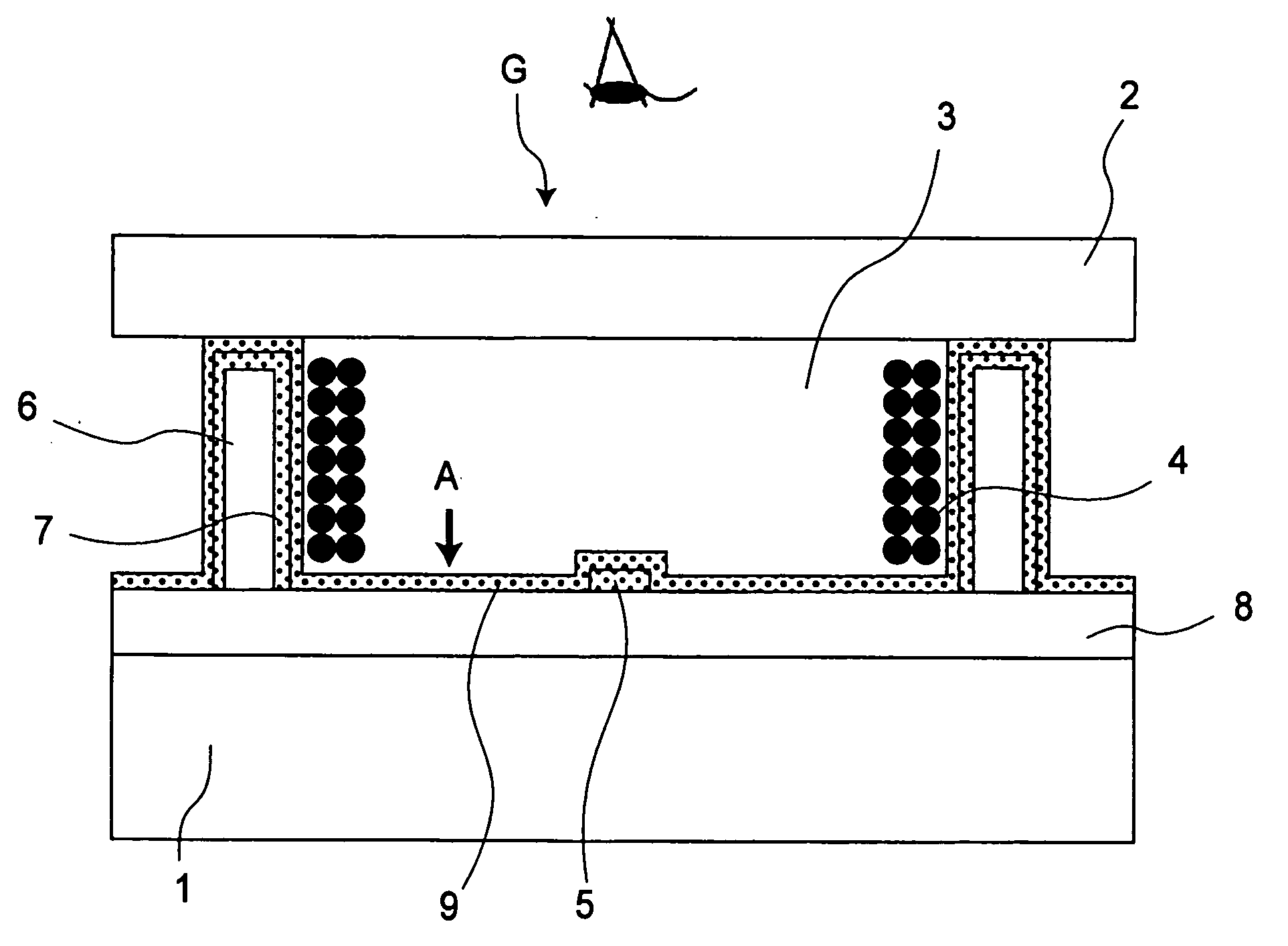
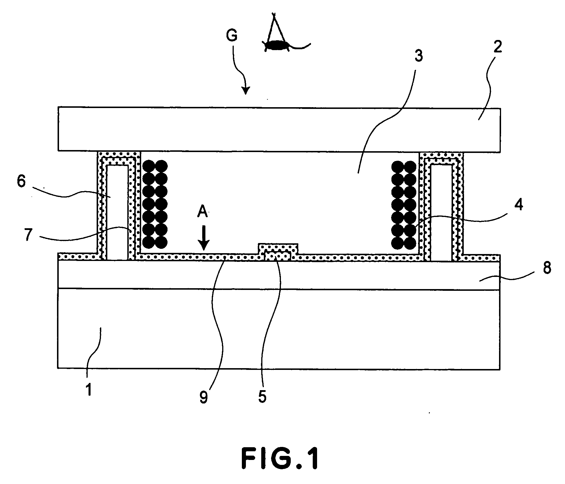
[0056]FIG. 1 shows a schematic structural view of an electrophoretic display device according to this embodiment of the present invention.

[0057] In FIG. 1, the electrophoretic display device includes a substrate 1, a sealing plate 2 disposed opposite to the substrate 1, and a pixel G. The sealing plate 2 is formed of a light-transmissive material, such as transparent glass or a transparent film. Incidentally, the substrate 1 is not necessarily required to be transparent and rigid and thus may be constituted by a film substrate, a metal substrate, or the like.

[0058] On the substrate 1, a display substrate-forming member 8 is formed of a transparent material or a material colored a desired color. Examples of the materials may include: plastics, such as acrylic resin, epoxy resin, silicone resin; and glass. In these materials, it is possible to mix inorganic oxide pigments, such as titanium oxide, zinc oxide, and aluminum oxide, or a dye to provide the material with color or light sc...

second embodiment

[0079]FIG. 6 is a schematic sectional view showing a constitution of an electrophoretic display device according to this embodiment. In FIG. 6, the same reference numerals as in FIG. 1 represent the same or corresponding portions as in FIG. 1.

[0080] In the electrophoretic display device shown in FIG. 6, an unevenness portion 13 is formed on a substrate 1 and a first electrode 12 is formed on an upper surface of the unevenness portion 13. The unevenness portion 13 can be formed by, e.g., applying a photosensitive resin onto the substrate 1 and then performing light exposure and wet development or by such a method that a minute unevenness is provided on a glass plate. As a material for the first electrode 12 formed on the unevenness portion 13, it is possible to use a material, having a high reflectance, such as Al or Ag.

[0081] As described above, by forming the first electrode 12 on the unevenness portion 13, it is possible to impart a light diffusion function to the first electrod...

third embodiment

[0090]FIG. 8 is a schematic sectional view showing a constitution of an electrophoretic display device according to this embodiment. In FIG. 8, the same reference numerals as in FIG. 6 represent the same or corresponding portions as in FIG. 6.

[0091] In the electrophoretic display device shown in FIG. 8, a connection material 12 is filled in the contact hole 11 in which the first electrode 5 and the resistance layer 9 are electrically connected through the connection material 12. By providing such a constitution, a stepwise portion at the surface of the resistance layer 9 can be reduced, so that it is possible to solve such a problem that the electrophoretic particles 4 are attached to the stepwise portion at the contact hole portion.

[0092] Incidentally, as a material for the connection material 12, a material having a low resistance than that of the resistance layer 9 is preferred. It is possible to use metal such as Al or Ti; ITO; electroconductive resin. When the resistance of t...


PUM

PropertyMeasurementUnit
sizeaaaaaaaaaa
sizeaaaaaaaaaa
thicknessaaaaaaaaaa

Abstract

An electrophoretic display device is constituted by a substrate, a partition wall disposed on a surface of the substrate; a liquid layer, disposed in a container defined by the substrate and the partition wall, comprising electrophoretic particles and a dispersion medium; a first electrode formed at a position apart from the partition wall on the substrate, a second electrode formed along the partition wall; and means for applying a voltage between the first electrode and the second electrode. At the surface of the substrate defining the container, a resistance layer electrically connecting the first electrode and the second electrode is formed, and the electrophoretic particles in the container are moved between a surface of the partition wall and a surface of the resistance layer to effect display.

Description

TECHNICAL FIELD [0001] The present invention relates to an electrophoretic display apparatus and a driving method thereof. BACKGROUND ART [0002] With development of information equipment, the needs for low-power and thin display apparatuses having grown, so that extensive study and development have been made on display apparatuses fitted to these needs. [0003] Such a display apparatus is used frequently outdoors particularly as a wearable PC (personal computer) or an electronic note pad, thus being desirable that it can save power consumption and space. For this reason, e.g., such a product that a display function of a thin display such as a liquid crystal display and means for inputting coordinate data are integrated, and direct input can be effected by pressing a display item on a display surface with a stylus or finger, has been commercialized. [0004] However, most of liquid crystal materials have no memory characteristic, so that it is necessary to continuously apply a voltage t...

Claims


Application Information

Patent Timeline
Patent Type & Authority Applications(United States)
IPC IPC(8): G09G3/34G02F1/167G09G3/20
CPCG02F1/167
Inventor NAGAYAMA, KOHEI
Owner CANON KK
Why Eureka
Try Eureka