Liquid crystal lens, photographing apparatus and flash light emitting unit

a technology of liquid crystal lens and flash light, which is applied in the field of liquid crystal lens, photographing apparatus and flash light emitting unit, can solve the problems of interfering with the miniaturization and weight saving of a light emitting unit, and difficult to make a focal length variable except an optical axis direction, etc., to achieve the effect of simplifying the configuration of the circuit, miniaturization and weigh

Inactive Publication Date: 2007-05-31
FUJIFILM CORP
View PDF3 Cites 20 Cited by
  • Summary
  • Abstract
  • Description
  • Claims
  • Application Information

AI Technical Summary

Benefits of technology

[0047] Hereby, it is possible to simplify configuration of the circuit which performs voltage application control to the selected liquid crystal pixels.
[0048] As described above, the present invention can provide the liquid crystal lens which can achieve miniaturization and weight saving of an apparatus, and can transmit light, which is incident, in an optical axis direction and also a direction other than the optical axis direction, and the image taking apparatus and the flash light emitting unit which are given miniaturization and weight saving, and can make an irradiation position and an irradiation angle of fill light variable.

Problems solved by technology

Since all the techniques which are proposed in Japanese Patent Laid-Open Nos. 57-122423, H2-196228, and H4-14029 require a mechanism of changing mechanical structure at the time of changing an irradiation direction and an irradiation angle of light variable, there arises a problem of interfering with miniaturization and weight saving of a light emitting unit.
Hence, there also arise a problem of interfering miniaturization and weight saving of a light emitting unit.
Furthermore, since the technique proposed in Japanese Patent Laid-Open Nos. 2002-357804 and 2005-18840 is a technique which makes a focal length variable in an optical axis direction, there is a problem that it is difficult to make a focal length variable except an optical axis direction.
Hence, it has a defect that a focal length of the lens in which the distance measurement fill light can cover is within a certain limited range, and it does not reach a distant position.
Here, although it is conceivable to enlarge a light source which emits distance measurement fill light, there arises a problem of interfering with miniaturization of an AF fill light emitting apparatus.

Method used


Image

  • Liquid crystal lens, photographing apparatus and flash light emitting unit
  • Liquid crystal lens, photographing apparatus and flash light emitting unit
  • Liquid crystal lens, photographing apparatus and flash light emitting unit

Examples


first embodiment

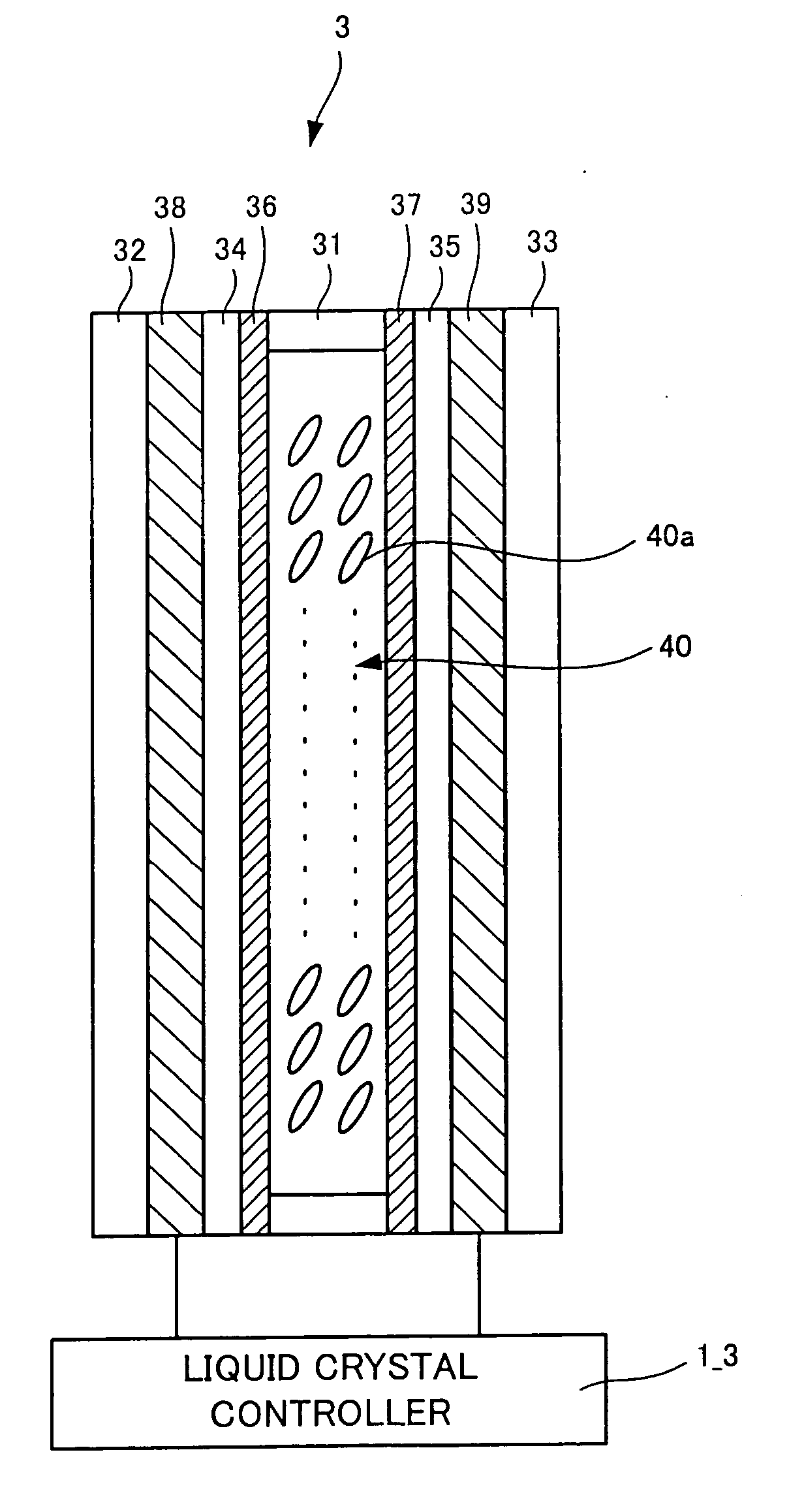
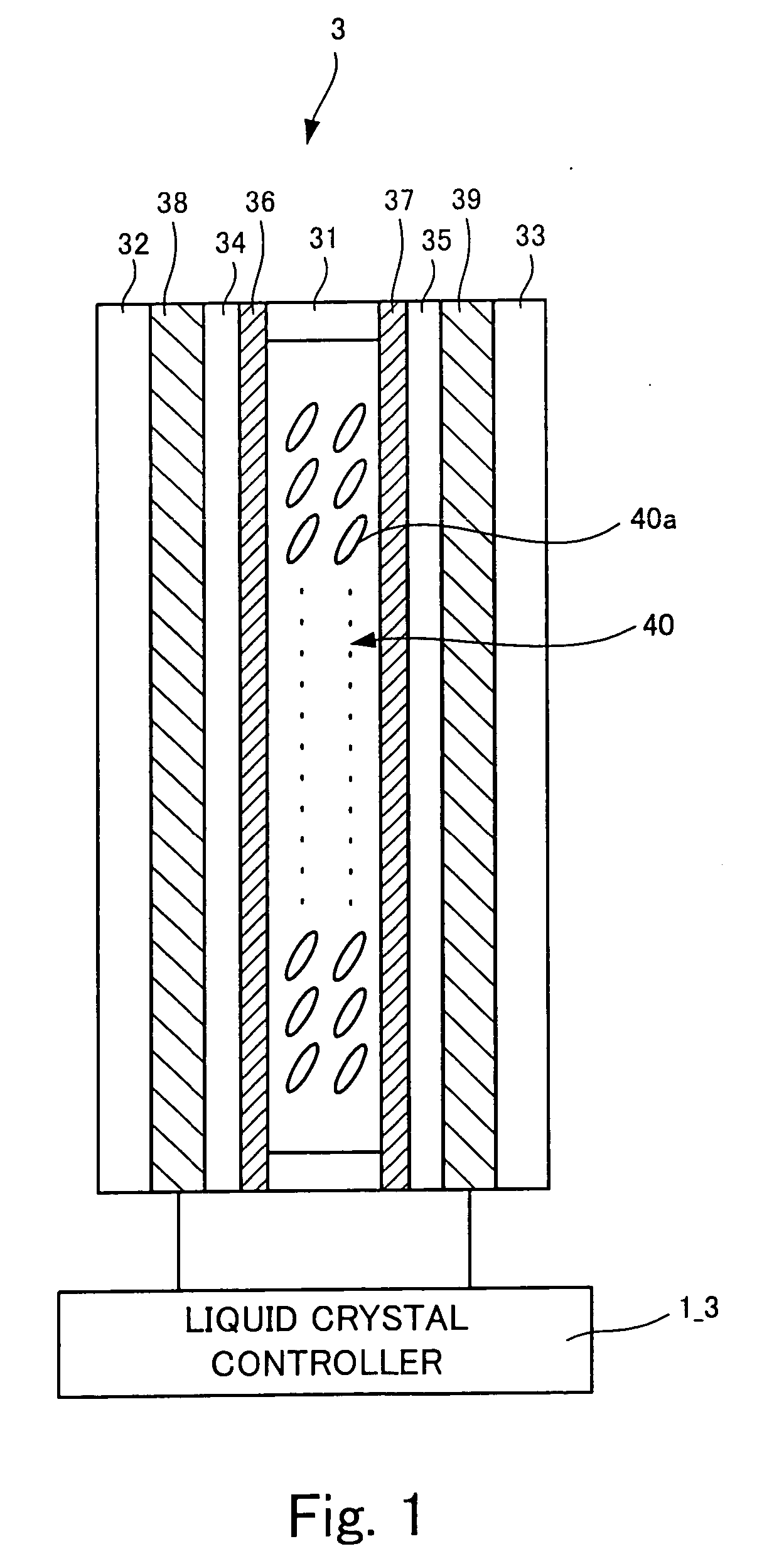
[0063]FIG. 1 is a sectional view of a liquid crystal lens of the present invention.

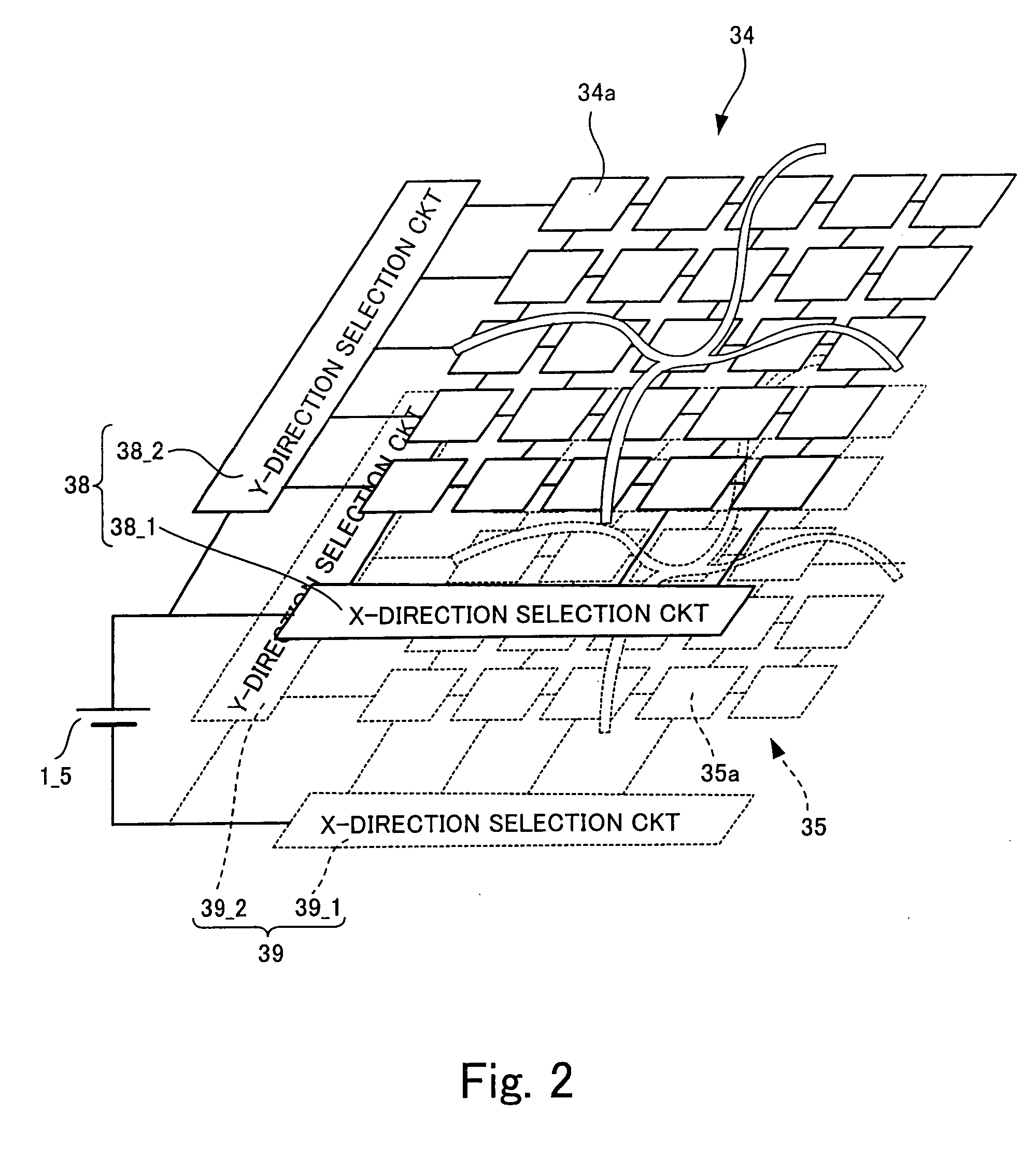
[0064] A liquid crystal lens 3 shown in FIG. 1 has a spacer 31, tabular transparent substrates 32 and 33 arranged oppositely through the spacer 31, transparent XY address selection sections 38 and 39 arranged inside the transparent substrates 32 and 33, transparent electrodes 34 and 35 arranged inside the transparent XY address selection sections 38 and 39, light distribution films 36 and 37 arranged inside the transparent electrodes 34 and 35, and liquid crystal 40 filled in a space defined by the spacer 31 and light distribution films 36 and 37. The liquid crystal 40 has liquid crystal molecules 40a.

[0065] The transparent substrates 32 and 33 are formed of a material which has a high transmission factor in a wavelength band of incident light, and glass, a high polymer film, or the like can be used for them.

[0066] The transparent electrodes 34 and 35 are equivalent to the examples of the optically ...

second embodiment

[0106]FIGS. 9A and 9B are external perspective views of a digital camera which is the image taking apparatus of the present invention, and FIG. 10 is a block diagram showing the circuit configuration of the digital camera shown in FIGS. 9A and 9B.

[0107] In addition, the same reference numerals are applied to the same components as the components of the digital camera 100 shown in FIGS. 5A and 5B, and FIG. 6, and only different points will be explained.

[0108] A digital camera 200 shown in 9B has a conventional flash light emitting unit 201, and the AF light emitting unit 2 and an AF light receiving section 202 which construct an auto-focusing (AF) apparatus generally called an active type. The AF light emitting unit 2 is a unit which assists an auto-focusing (AF) function by emitting distance measurement fill light at the time of image taking under low illuminance. As shown in FIG. 10, this AF light emitting unit 2 has the liquid crystal lens 3 mentioned above, liquid crystal contro...


PUM


Abstract

The liquid crystal lens of the invention has an optically transparent liquid crystal plate which includes a plurality of liquid crystal pixels divided two-dimensionally, and a liquid crystal drive section which selects only a part of the liquid crystal pixels simultaneously and controls voltage application to the selected liquid crystal pixels. The liquid crystal drive section performs voltage application control to the selected liquid crystal pixels so as to form, in the liquid crystal plate, a refractive index distribution of light which transmits the liquid crystal plate.

Description

BACKGROUND OF THE INVENTION [0001] 1. Field of the Invention [0002] The present invention relates to a liquid crystal lens which uses a liquid crystal and in which a refractive index changes according to an applied voltage, and to an image taking apparatus which has an image taking optical system with a variable focal length, captures an object image which is incident through the image taking optical system, and generates image data, and to a flash light emitting unit. [0003] 2. Description of the Related Art [0004] In a camera which is one of image taking apparatuses, flash light as image taking fill light is radiated toward an object from a light emitting unit in synch with a shutter operation when object brightness is insufficient in image taking. What is known as a light emitting unit is a light emitting unit including an arc tube which emits flash light, and a reflector which reflects the flash light emitted from the arc tube (reflective shade). [0005] As such a light emitting ...

Claims


Application Information

Patent Timeline
Patent Type & Authority Applications(United States)
IPC IPC(8): G03B21/32G03B19/18
CPCG02F1/139G02F1/292G03B17/04G03B2215/0503G09G3/3622H04N5/2256H04N5/2354H04N23/56H04N23/74
Inventor MISAWA, TAKESHIENDO, HIROSHIKATO, TAKASHIMIYANO, HITOSHI
Owner FUJIFILM CORP
Why Eureka
Try Eureka