Method and apparatus for dynamic impact testing

a technology of dynamic impact testing and method, applied in the direction of material strength testing, material analysis, instruments, etc., can solve the problems of often considered impracticality, and achieve the effects of easy attachment or removal, easy adaptation, and modification of the shape and mass of the projectil

Inactive Publication Date: 2007-06-07
SEMICON COMPONENTS IND LLC
View PDF16 Cites 17 Cited by
  • Summary
  • Abstract
  • Description
  • Claims
  • Application Information

AI Technical Summary

Benefits of technology

[0007] Actual environmental conditions can be simulated through modification of the stopper assembly. The shape and mass of the projectile may be altered. The stopper assembly is typically configured to be easily attached or removed from the lower end of the rod thereby allowing the apparatus to be readily adapted for testing a wide variety of materials and objects, including: metals, ceramics, semiconductors, semiconductor wafers, insulators, ICs, IC dies and printed circuit boards. Further, the tip of the stopper assembly may be constructed in a variety of shapes, permitting the area of impact to be finely controlled. The tip of the stopper assembly can be manufactured from a variety of materials possessing different hardness, elasticity and other properties. The diameter and profile of the stopper assembly washer may be varied to ensure optimal transfer of energy to the selected stopper tip. In certain embodiments, the stopper tip contacts the test material or object prior to impact by the projectile thereby allowing the force of impact to be directed with precision to a selected point or area of impact on the test material or object. Typically, the level of impact force imparted to the stopper assembly can be precisely controlled and measured. Thus, the apparatus is capable of accurately simulating actual environmental conditions observed in real-life impacts, including the impact experienced by falling materials or objects.

Problems solved by technology

Materials and objects used in the manufacture of semiconductor ICs are measured in inches or fractions of inches and dynamic impact testing of such materials and objects has, in the prior art, often been considered impractical because of the small size of the materials and objects.

Method used


Image

  • Method and apparatus for dynamic impact testing
  • Method and apparatus for dynamic impact testing
  • Method and apparatus for dynamic impact testing

Examples


Embodiment Construction

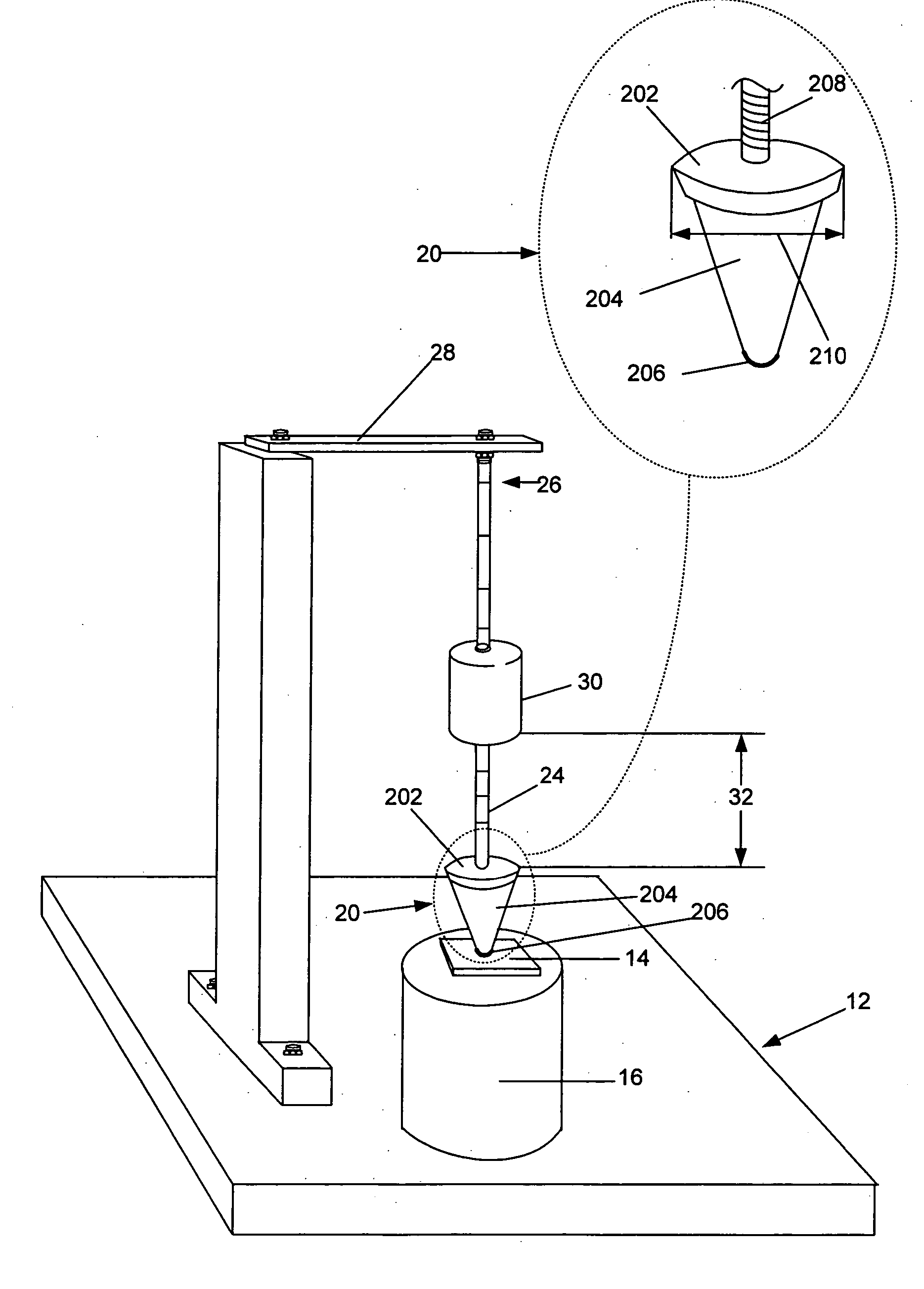
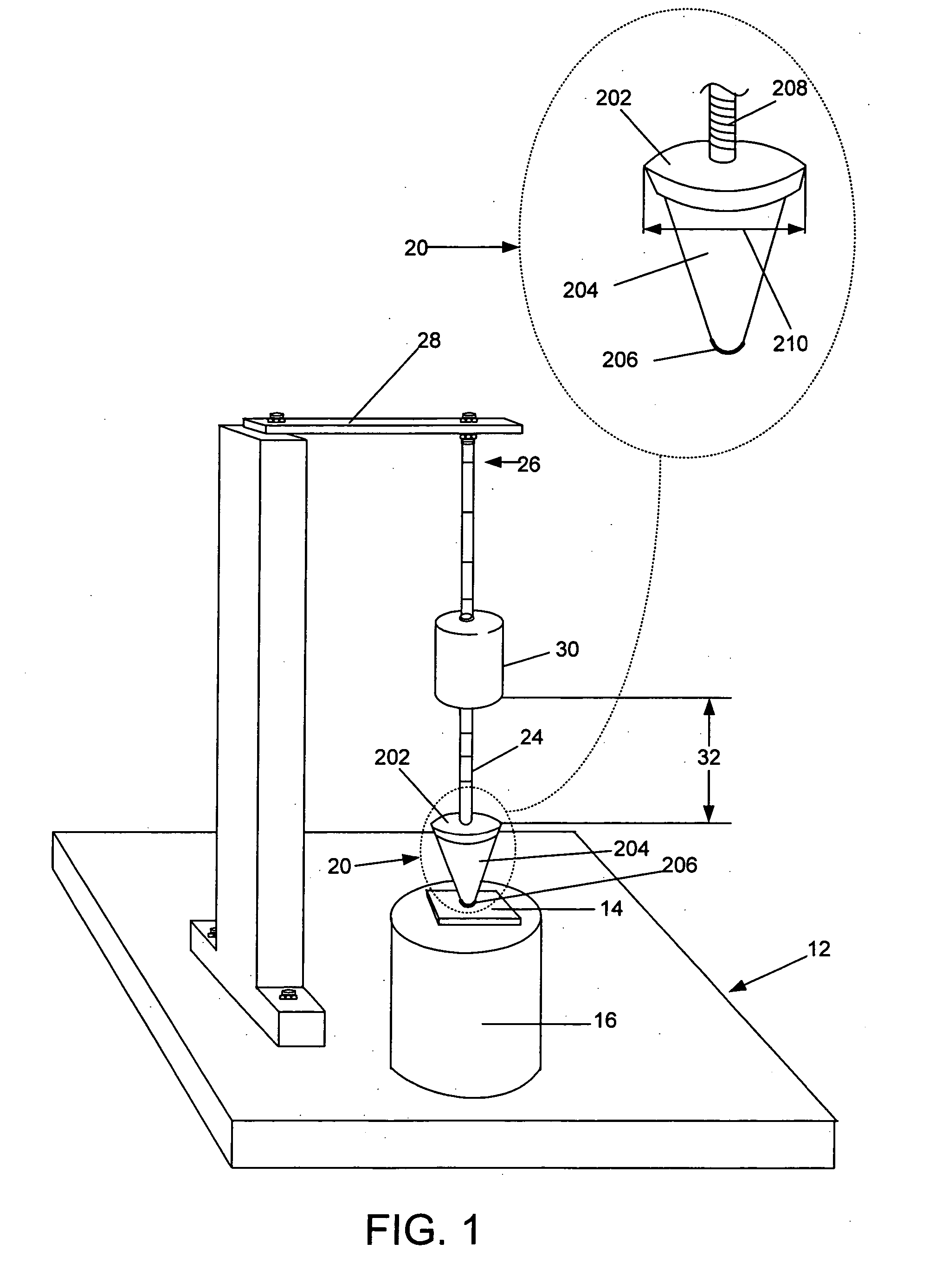
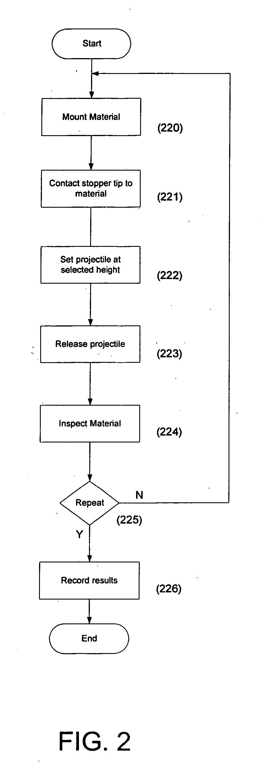
[0020] Embodiments of the present invention will now be described in detail with reference to the drawings, which are provided as illustrative examples so as to enable those skilled in the art to practice the invention. Notably, the figures and examples below are not meant to limit the scope of the present invention. Wherever convenient, the same reference numbers will be used throughout the drawings to refer to same or like parts. Where certain elements of these embodiments can be partially or fully implemented using known components, only those portions of such known components that are necessary for an understanding of the present invention will be described, and detailed descriptions of other portions of such known components will be omitted so as not to obscure the invention. Further, the present invention encompasses present and future known equivalents to the components referred to herein by way of illustration.

[0021] Referring to FIG. 1, certain embodiments of the invention...


PUM

PropertyMeasurementUnit
massaaaaaaaaaa
impact angleaaaaaaaaaa

Abstract

A method and apparatus wherein a material or object to be tested is placed on a base support. A stopper assembly having a stopper tip on one end in contact with the test material or object, and a washer on the opposite end attached to a rod. A projectile is propelled with a selected level of force along the rod and impacts the washer, which transmits the force of impact through the stopper tip to the test material or object. The level of propelling force, the mass of the projectile, the construction of the stopper assembly and the location of impact on the test material or object may be precisely adjusted to simulate real-life impacts.

Description

BACKGROUND OF THE INVENTION [0001] 1. Field of the Invention [0002] The present invention relates generally to methods and apparatus for dynamic impact testing of materials or objects and more particularly to a method and apparatus for dynamic impact testing of materials or objects when force is applied to the materials or objects by impact with an accelerated projectile. The present invention has particular application in testing materials and objects related to integrated circuit (IC) production. [0003] 2. Description of the Prior Art [0004] Dynamic impact testing is a load displacement test method in which a material or object is subjected to an impact force. The purpose of the dynamic impact test is to determine the resilience of a material or object under rough handling. Dynamic impact testing is often performed to ascertain the level of force required to cause the structure of a material or object to fail. Dynamic impact testing typically involves dropping a projectile from a ...

Claims


Application Information

Patent Timeline
Patent Type & Authority Applications(United States)
IPC IPC(8): G01N3/30
CPCG01N3/303
Inventor BRANKOV, ANGUEL S.
Owner SEMICON COMPONENTS IND LLC
Why Eureka
Try Eureka