Infrared diffractive lens
a diffractive lens and infrared technology, applied in the field of infrared diffractive lenses, can solve the problems of varying the focal length of the lens according to the frequency and the above problem becomes serious
- Summary
- Abstract
- Description
- Claims
- Application Information
AI Technical Summary
Benefits of technology
Problems solved by technology
Method used
Image
Examples
first embodiment
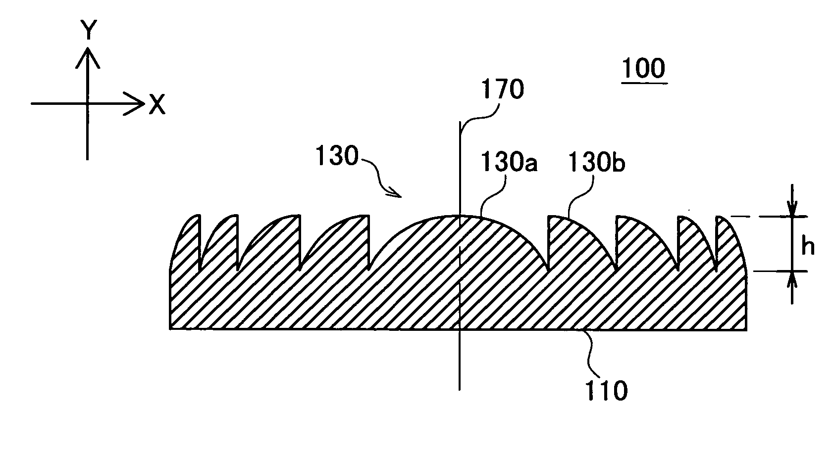
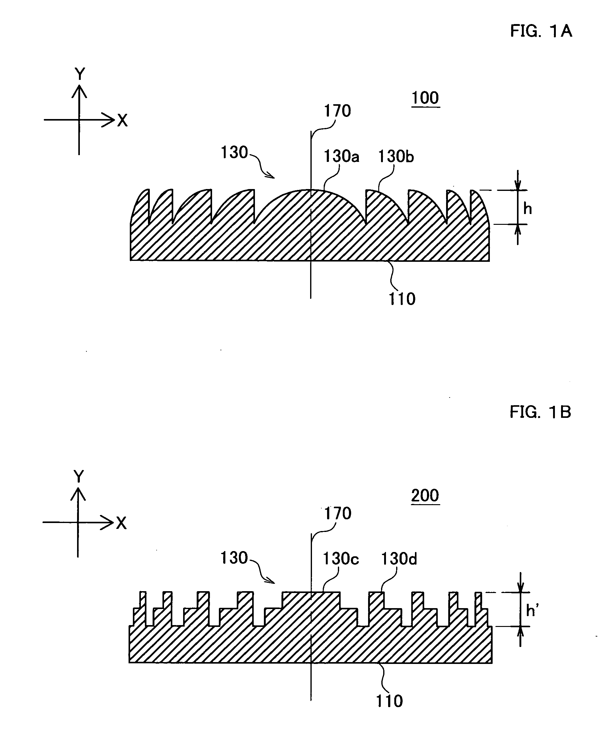
[0095] Simulation is performed similarly to the comparative example except that the design wavelength of the harmonic order m of the infrared diffractive lens 100 is set at 3. FIGS. 7A and 7B show the simulation result. FIG. 7A is a graph chart showing a relation between diffraction efficiency of the infrared diffractive lens and infrared wavelength. FIG. 7B is a graph chart showing an efficiency of reception of the infrared rays transmitted through the infrared diffractive lens at an infrared receiver.
[0096] Referring to FIG. 7A, the diffraction efficiency also becomes 100% at 6 μm (diffraction order k=4) as well as 8 μm of the design wavelength (diffraction order k=3) and there is diffracted in the same diffraction direction as the infrared rays with the wavelength at 8 μm. In addition, the infrared rays at k=4 also contributes greatly as well as the infrared rays at k=3 among the diffraction efficiencies in the whole infrared rays transmitted actually through the infrared diffra...
second embodiment
[0098] Simulation is performed similarly to the comparative example except that the design wavelength of the harmonic order m of the infrared diffractive lens 100 is set at 5. FIGS. 8A and 8B show the simulation result. FIG. 8A is a graph chart showing a relation between diffraction efficiency of the infrared diffractive lens and infrared wavelength. FIG. 8B is a graph chart showing an efficiency of reception of the infrared rays transmitted through the infrared diffractive lens at an infrared receiver.
[0099] Referring to FIG. 8A, the diffraction efficiency also becomes 100% at 6.6 μm (diffraction order k=6) and 10 μm (diffraction order k=4) as well as 8 μm of the design wavelength (diffraction order k=5) and the infrared rays with the wavelengths of 6.6 μm and 10 μm are diffracted in the same diffraction direction as in the infrared rays with the wavelength at 8 μm.
[0100] Referring to FIG. 8B, compared to the first embodiment (m=3), the light-receiving efficiency improves signifi...
third embodiment
[0101] Simulation is performed similarly to the comparative example except that the design wavelength of the harmonic order m of the infrared diffractive lens 100 is set at 7. FIGS. 9A and 9B show the simulation result. FIG. 9A is a graph chart showing a relation between diffraction efficiency of the infrared diffractive lens and infrared wavelength. FIG. 9B is a graph chart showing an efficiency of reception of the infrared rays transmitted through the infrared diffractive lens at an infrared receiver.
[0102] Referring to FIG. 9A, the diffraction efficiency also becomes 100% at least at four wavelengths of 6.2 μm (diffraction order k=9), 7 μm (diffraction order k=8) and 9.4 μm (diffraction order k=6) as well as 8 μm of the design wavelength (diffraction order k=7) and the infrared rays with the four wavelengths are diffracted in the same diffraction direction.
[0103] Referring to FIG. 9B, there can be obtained the light-receiving efficiency at 80% or higher in the wavelength band a...
PUM
 Abstract
Description
Claims
Application Information
 - R&D
- Intellectual Property
- Life Sciences
- Materials
- Tech Scout
- Unparalleled Data Quality
- Higher Quality Content
- 60% Fewer Hallucinations
Browse by: Latest US Patents, China's latest patents, Technical Efficacy Thesaurus, Application Domain, Technology Topic, Popular Technical Reports.
© 2025 PatSnap. All rights reserved.Legal|Privacy policy|Modern Slavery Act Transparency Statement|Sitemap|About US| Contact US: help@patsnap.com


