
Sintered body for magnetic head slider, magnetic head slider, and method of producing sintered body for magnetic head slider

a technology of magnetic head slider and sintered body, which is applied in the direction of maintaining head carrier alignment, recording information storage, instruments, etc., can solve the problems of large level difference and large polishing amount of laminate, and achieve the effect of reducing the level difference of air bearing surface, reducing surface roughness, and reducing surface roughness

Inactive Publication Date: 2007-06-07
TDK CORPARATION
View PDF3 Cites 4 Cited by
  • Summary
  • Abstract
  • Description
  • Claims
  • Application Information

AI Technical Summary

Benefits of technology

[0009] The present invention has been accomplished in view of the above problem and an object of the invention is to provide a sintered body for a magnetic head slider achieving reduction in the level difference of the air bearing surface and having adequate surface smoothness of the polished surface, a magnetic head slider using it, and a method of producing the sintered body for the magnetic head slider.
[0024] The present invention successfully achieves the magnetic head slider having adequate surface smoothness of the air bearing surface and the reduced level difference of the air bearing surface. This permits us to produce the magnetic head slider in a smaller size and to achieve higher density of recording.

Problems solved by technology

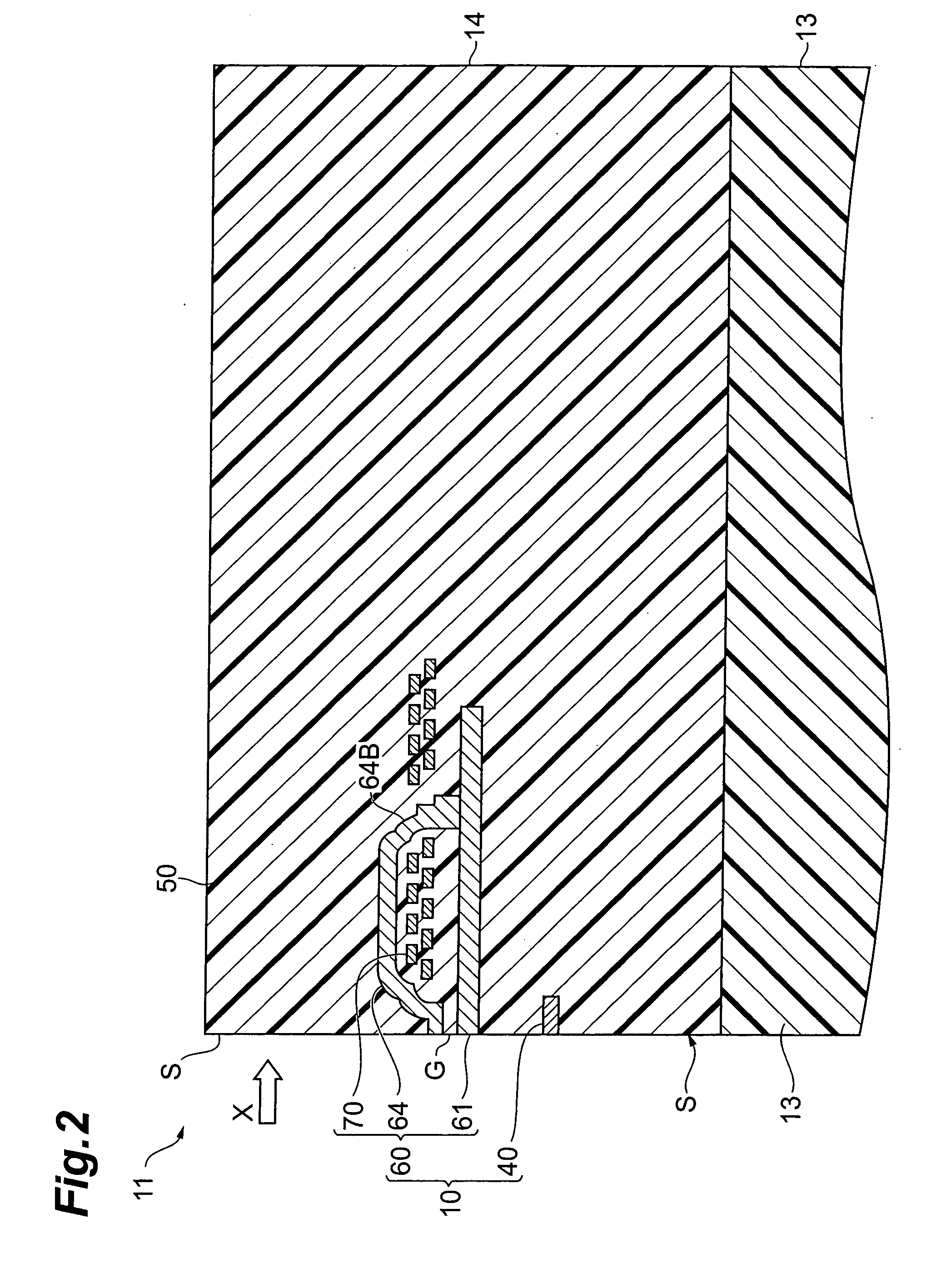
The Inventors conducted elaborate research and discovered that a polishing rate of the AlTiC sintered body used as the substrate of the conventional magnetic head slider was much smaller than a polishing rate of the laminate incorporating the thin-film magnetic head and that it caused the polishing amount of the laminate to become much larger than the polishing amount of the substrate during the lapping, resulting in the large level difference.

Method used


Image

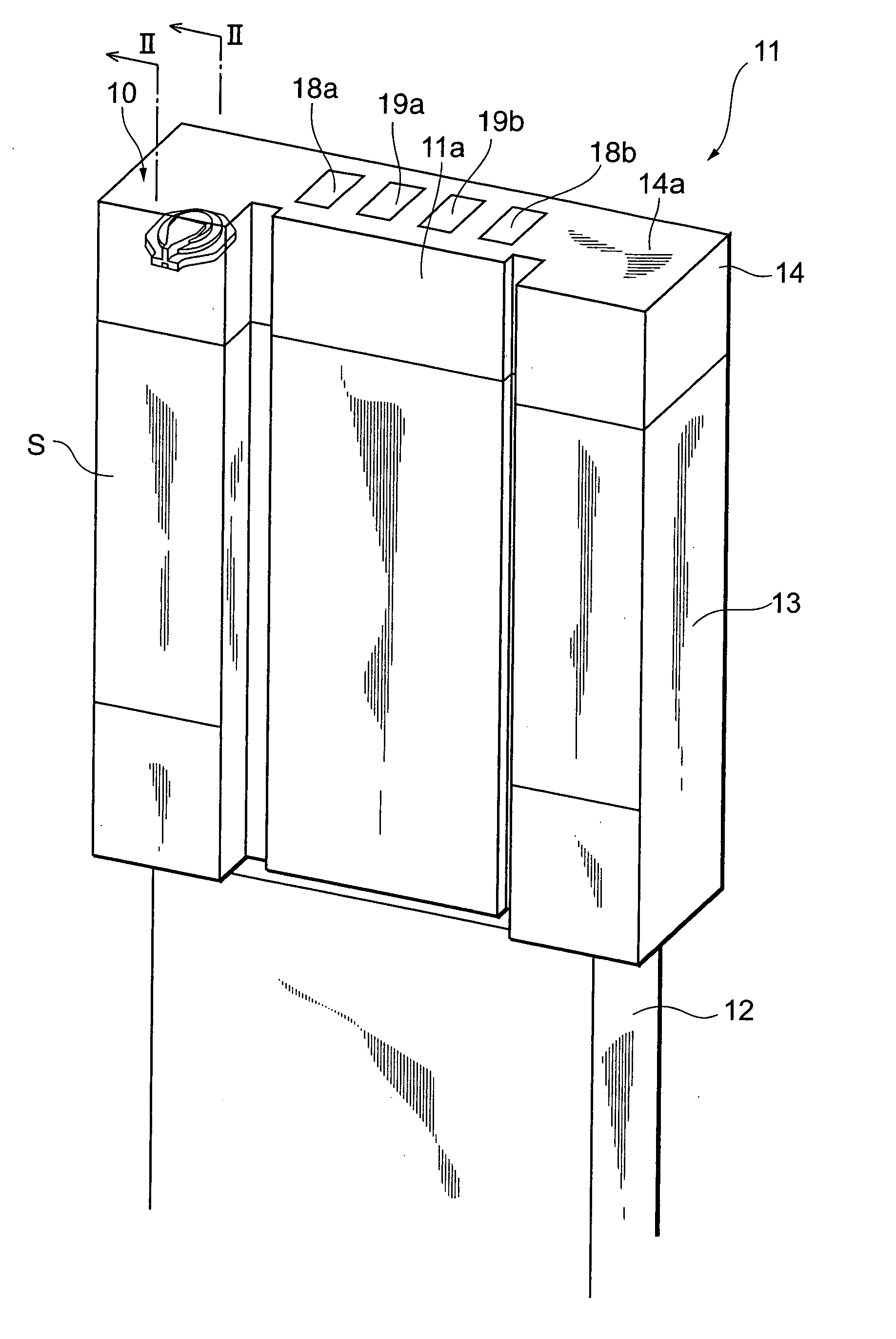
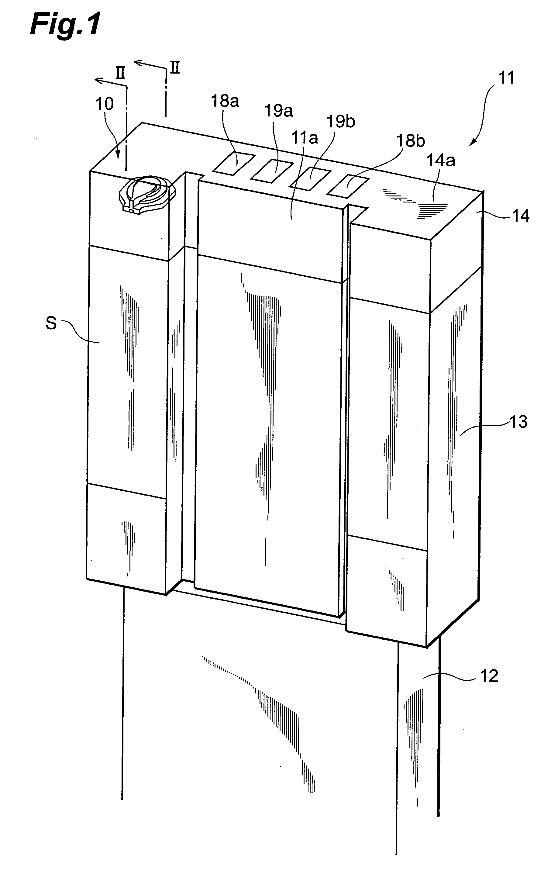
  • Sintered body for magnetic head slider, magnetic head slider, and method of producing sintered body for magnetic head slider
  • Sintered body for magnetic head slider, magnetic head slider, and method of producing sintered body for magnetic head slider
  • Sintered body for magnetic head slider, magnetic head slider, and method of producing sintered body for magnetic head slider

Examples


examples

[0097] The present invention will be described below in further detail with examples and comparative examples, but it is noted that the present invention is by no means intended to be limited to these examples.

[0098] In the examples, a plurality of substrates were made from sintered bodies for the magnetic head slider different in constituent materials and the polishing rate and surface roughness were measured for each of them.

examples 1-9

[0099] First, an Al2O3 powder (average particle size 0.5 μm), a TiC powder (average particle size 0.3 μm and carbon content 0.1 wt %), a WC powder (average particle size 0.1 μm and carbon content 0.1 wt %), a TiO2 powder (average particle size 0.6 μm), and a carbon powder (carbon black, average particle size 35 nm) were weighed by predetermined amounts, respectively, they were pulverized with IPA (isopropyl alcohol; boiling point 82.4° C.) in a ball mill for 30 minutes, and thereafter they were spray-granulated at 150° C. in nitrogen to obtain granules.

[0100] The Al2O3 powder, TiC powder, WC powder, carbon powder, and TiO2 powder were mixed in the contents satisfying the conditions in FIG. 6, in the granules. The volume ratios and molar ratios are data converted from weight ratios on the basis of the real densities and molecular weights. The real densities of Al2O3, TiC, WC, TiO2, and carbon used were 3990, 4920, 15770, 4260, and 2000 kg / m3, respectively.

[0101] Subsequently, the r...


PUM

PropertyMeasurementUnit
particle sizeaaaaaaaaaa
diameteraaaaaaaaaa
pressureaaaaaaaaaa

Abstract

A sintered body for a magnetic head slider has at least one of TiC and XC, a carbide containing Ti and X, Al2O3, and free carbon, contains 25 to 160 parts by volume of all the carbides including at least one of TiC and XC, and the carbide containing Ti and X, based on 100 parts by volume of Al203, and contains 1 to 15 parts by volume of free carbon, based on 100 parts by volume of a total of Al2O3 and all the carbides (where X is at least one element selected from the group consisting of Ta, W, Mo, Nb, Zr, V, and Cr).

Description

BACKGROUND OF THE INVENTION [0001] 1. Field of the Invention [0002] The present invention relates to a sintered body for a magnetic head slider, a magnetic head slider, and a method of producing a sintered body for a magnetic head slider. [0003] 2. Related Background Art [0004] A magnetic head slider incorporating a thin-film magnetic head was first used in a hard disk drive in 1979, and the magnetic head slider at that time is commonly called a mini slider (100% slider). The magnetic head sliders have been downsized through a micro slider (70% slider) having the size of about 70% of the mini slider to a nano slider (50% slider) having the size of about 50% of the mini slider. [0005] Such magnetic head sliders are normally constructed with a laminate incorporating a thin-film magnetic head on a substrate. The magnetic head sliders of this type are obtained by laying the laminate incorporating the thin-film magnetic head, on the substrate to form a laminated structure, thereafter cut...

Claims


Application Information

Patent Timeline
Patent Type & Authority Applications(United States)
IPC IPC(8): G11B5/60
CPCG11B5/3106G11B5/6005C04B35/117C04B35/5607C04B35/5626C04B35/62695C04B35/645C04B35/6455C04B2235/3217C04B2235/3232C04B2235/3826C04B2235/3839C04B2235/3843C04B2235/3847C04B2235/422C04B2235/5445
Inventor SUGIURA, KEIKAWAGUCHI, YUKIO
Owner TDK CORPARATION
Learn More