Transfer paper for electrophotography and manufacturing method thereof

a technology of transfer paper and electrophotography, which is applied in the field of transfer paper for electrophotography, can solve the problems of increasing the weight, affecting the image quality, and the paper becoming easier to break, and achieves the effects of high paper feeding conveyability, high image quality, and sufficient surface smoothness

Inactive Publication Date: 2005-06-28
CANON KK
View PDF7 Cites 0 Cited by
  • Summary
  • Abstract
  • Description
  • Claims
  • Application Information

AI Technical Summary

Benefits of technology

[0009]More specifically, the present invention aims at ensuring a high paper feeding conveyability in a transfer material for electrophotography used in an electrophotographic device or an electrostatic recorder, and obtaining a surface smoothness sufficient to achieve a high image quality.
[0010]A second object of the invention is to provide a transfer sheet of paper which permits prevention of the above-mentioned problems even including occurrence of blisters by making contrivances in the coating method.

Problems solved by technology

It has however been discovered that, when using such coated paper in electrophotography, heat pressurization through fixing rollers may sometimes cause blisters.
As a result, the proposed technique is not applicable to ordinary coated paper.
A problem intrinsic to coated paper is that, for the purpose of achieving smoothness of the surface, it is the usual practice to apply a smoothing treatment known as a calendar treatment in the final stage during formation of a coated layer on the paper.
In this smoothing treatment, however, a problem of the paper becoming easier to break is encountered.
This leads to the necessity to increase the weight.
When applying coating on such a printer, however, smoothness of paper is unavailable because of occurrence of print seams, but on the contrary, it is necessary to apply a pressure with a view to leveling the surface.

Method used


Image

  • Transfer paper for electrophotography and manufacturing method thereof
  • Transfer paper for electrophotography and manufacturing method thereof
  • Transfer paper for electrophotography and manufacturing method thereof

Examples


example 1

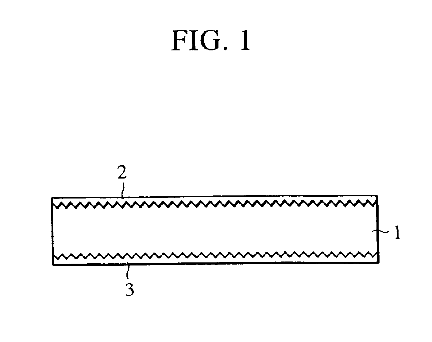
[0057]Titanium oxide in an amount of 6 wt. % in dry weight standard, 6 wt. % kaolin, 0.5 wt. % aluminum sulfate, 0.3 wt. % rosin sizing agent, and 3.2 wt. % water-soluble binder were mixed to L.B.K.P. (broadleaf pulp). Papermaking was carried out in a long-mesh papermaking machine by use of a pulp suspension after adjustment with water, and the resultant paper was dried. A wood-free paper product of which the water contact was adjusted to 5% after papermaking was obtained.

[0058]A white pigment (calcium carbonate) in an amount of two weight parts was mixed to 150 weight parts coating acrylic resin for coating. A coating solution prepared by diluted with toluene was coated on a side of the wood-free paper with a gravure coater, thereby forming a coated layer on the back. The coated layer was dried to a weight of 8 g / m2.

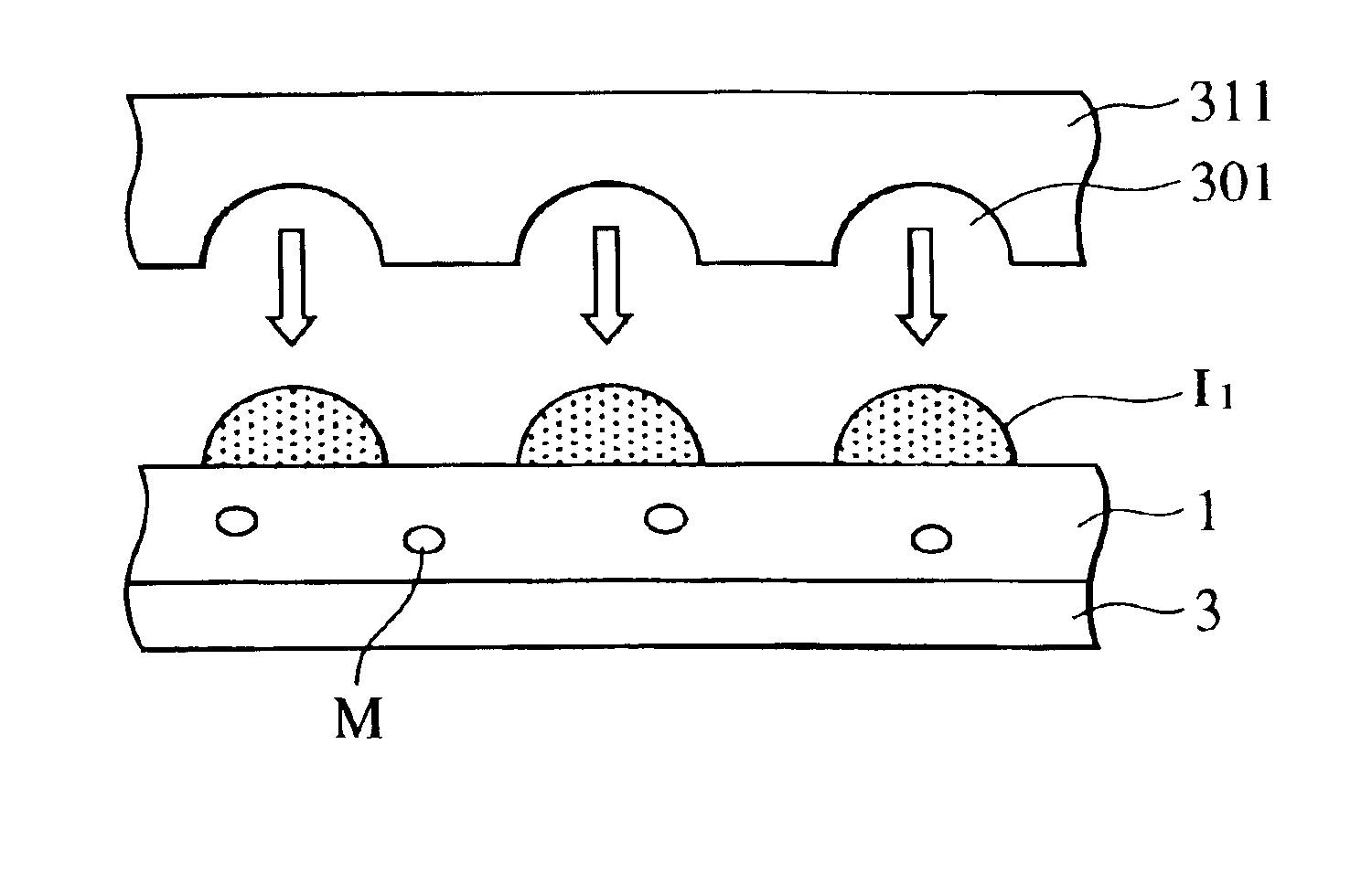
[0059]The above-mentioned coating solution was coated in an amount of 4.2 g / m2 (coating weight after drying) on the surface not coated with the above-mentioned back coa...

example 2

[0063]Transfer paper having a total weight of 108 g / m2 was manufactured in the same manner as in Example 1 except that, upon forming a transfer surface side coated layers, a silk screen printer having 80 / mm2 75 μm×75 μm square openings was used in place of the gravure printer; the coating weight of a first coated layer was changed to 2.5 g / m2 (coating weight after drying); a second coated layer having a different print seam was formed on the silk screen printer having 80 / mm2 75 μm×75 μm square openings arranged on the surface so that the concavity of a convex / concave pattern of the first coated layer was aligned with the convex portion of the second coated layer; and the coating weight of the second coated layer was changed to 3.5 g / m2 (coating weight after drying).

[0064]The resultant transfer paper had a CD-direction Clerk rigidity of 16 cm, and an arithmetic mean roughness (Ra) of 1.2 μm.

[0065]As a result of evaluation of this transfer paper in the same manner as in Example 1, a h...

example 3

[0066]Transfer paper was manufactured in the same manner as in Example 1 except that 150 weight parts coating urethane resin and 10 weight parts white pigment were used in place of 150 weight parts coating acrylic resin and 2 weight parts white pigment. The resultant transfer paper had a CD-direction Clerk rigidity of 17.4 cm, and an arithmetic mean roughness (Ra) of 1.25 μm.

[0067]An evaluation as in Example 1 was applied to this transfer paper. As a result, a high-quality image as shown in Table 1 was obtained without occurrence of fixing-twining or blisters.


PUM

PropertyMeasurementUnit
surface roughnessaaaaaaaaaa
pressureaaaaaaaaaa
particle sizeaaaaaaaaaa

Abstract

The present invention has an object to provide transfer paper for electrophotography which is excellent in paper-feed conveyability and image quality. The invention provides transfer paper for electrophotography having coated layers on both sides of a substrate material, comprising a first coated layer, containing a print seam, provided on at least one side thereof and a second coated layer provided on said first coated layer and having a print seam different from that of the first coated layer; wherein the total weight of the transfer paper for electrophotography is within a range from 60 to 130 g/m2. The manufacturing method of the transfer paper for electrophotography according to the present invention comprises a first coating step for coating a first coated layer having a print seam on at least one of the sides; a drying step for drying the first coated layer formed in the first coating step; and a second coating step for coating a second coated layer having a print seam different from the first print seam, over the dried first coated layer; wherein the transfer paper for electrophotography has a total weight within a range of from 60 to 130 g/m2.

Description

BACKGROUND OF THE INVENTION[0001]1. Field of the Invention[0002]The present invention relates to transfer paper for electrophotography having coated layers on both sides used in an electrophotographic device, an electrostatic recorder or the like, which ensures a high paper feedability and conveyability and provides a high image quality in electrophotography.[0003]2. Description of the Related Art[0004]In the area of electrophotography, digitalization of color recording devices has recently made a remarkable progress, and efforts have been made to achieve a higher image quality. Along with this tendency, in the sector of on-demand publishing, color copying machines and color printers are employed more and more popularly because of the possibility to more easily publish a smaller number of books for a title. These printed matters are now manufactured by means of copying machines and printers.[0005]Coated paper used generally for printing, known as art paper or coated paper, has been ...

Claims


Application Information

Patent Timeline
Patent Type & Authority Patents(United States)
IPC IPC(8): G03G7/00
CPCG03G7/00G03G7/0006G03G7/0053G03G7/0086Y10T428/24934Y10T428/24355Y10T428/24802
Inventor OGURA, MOTOHIRO
Owner CANON KK
Why Eureka
Try Eureka