
Method of manufacturing precision glass spheres and method of manufacturing optical glass elements

a technology of optical glass elements and precision glass spheres, which is applied in the manufacture of tools, sports equipment, skating, etc., can solve the problems of large amount of waste product (glass shavings), large amount of material consumed in processing, and time-consuming processing

Inactive Publication Date: 2005-09-29
HOYA CORP
View PDF3 Cites 7 Cited by
  • Summary
  • Abstract
  • Description
  • Claims
  • Application Information

AI Technical Summary

Benefits of technology

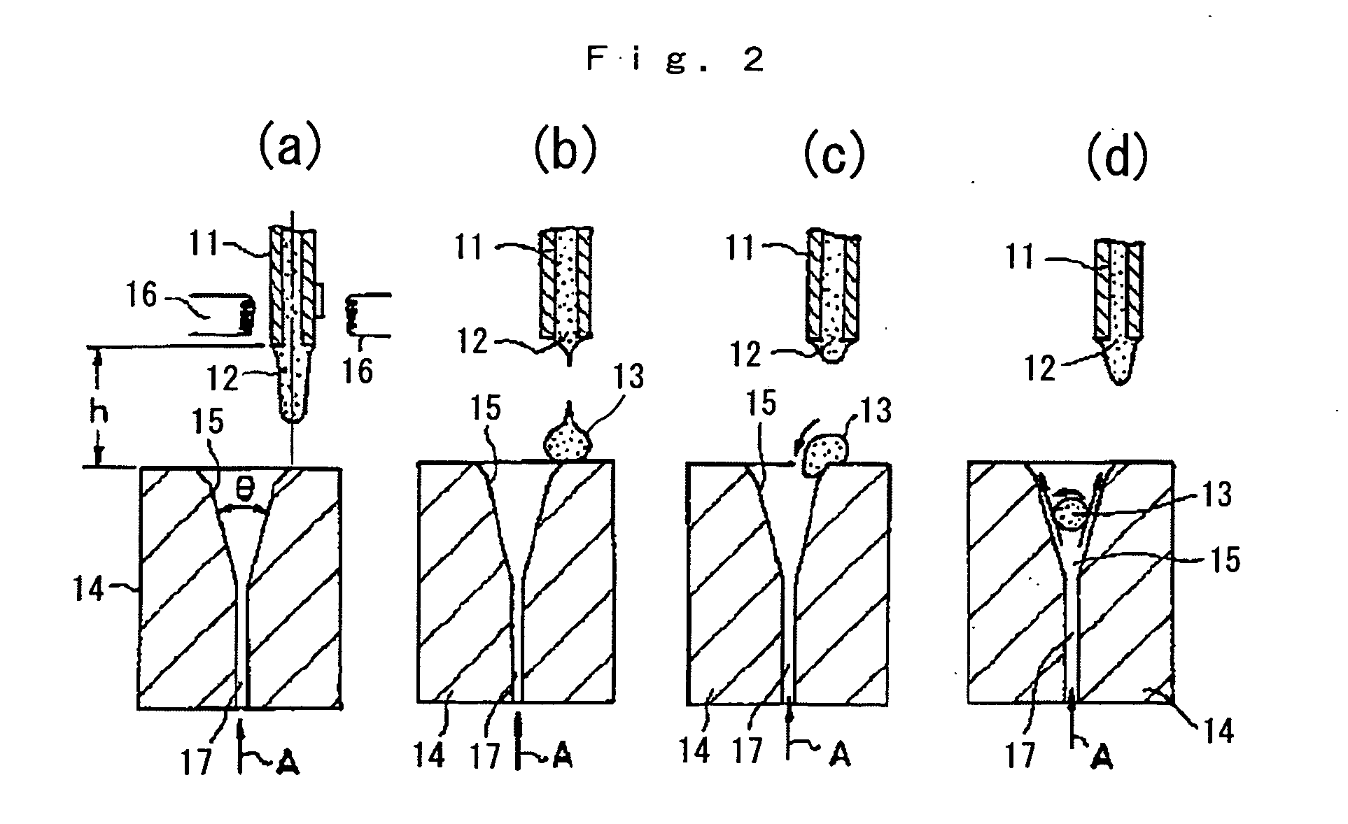
[0037] In the present invention, a crude glass sphere slightly larger than the dimensions of a desired precision glass sphere is formed by dripping glass melt, and an optically inhomogeneity layer formed on the surface thereof is removed by polishing to manufacture a precision glass sphere. By forming on a receiving mold the glass melt gob obtained by dripping, a crude glass sphere having approximately adequate surface smoothness can be shaped, readily yielding a crude glass sphere in which the variation in shape precision is within tolerances for a glass material used in precision press molding, with dimensions that are only slightly larger than those after final finishing. Accordingly, since it suffices to remove from the surface only the portion corresponding to the optically inhomogeneity layer in the polishing process and since the polishing allowance is quite small, advantages are achieved in the form of production efficiency and a reduction in the glass slurry discharged, the latter also being environmentally desirable. Further, it is difficult to eliminate throughout mass production the generation in some glasses of an optically inhomogeneity layer on the crude glass sphere caused by hot forming in the process of producing the glass material employed in precision press molding. However, the present invention provides a glass material not having an optically inhomogeneity layer for use in precision press molding, which is of great significance to mass production.

Problems solved by technology

However, the above-mentioned methods present the following problems.
Thus, the processing takes time, considerable material is consumed in processing, and a large amount of waste product (glass shavings, glass grindings, or a grinding slurry that is difficult to reuse) is produced.
Thus, disposal and processing present environmental issues.
Further, since the shape of the cubic or cylindrical glass material differs greatly from the shape of the optical element that is being molded and is of inadequate surface smoothness, molding efficiency is poor and optical properties such as surface precision are inadequate.
In the same manner as in the above method where a glass block is cold processed by cutting and grinding, there are problems in that the grinding allowance is large, production efficiency is poor, and a large quantity of grinding dust is discharged.
This is problematic in that the processing allowance, at 1.2 mm or more along the outer diameter and 44 percent or more in terms of weight, is quite large.
Even when boric acid is incorporated as a glass network component, volatilization of the boric acid tends to cause surface striae.
However, in that case, as well, the alkali component is volatile and tends to cause surface striae in the glass spheres.
When the outflow temperature is high, the amount of glass component volatizing during that period increases to a level that cannot be ignored, causing surface striae.
Due to glass characteristics such as those set forth above, there are problems in that an optically inhomogeneity layer containing striae and bubbles near the surface tends to form in the method described in Reference 3, and glass compositions suited to mass production are limited.
Thus, when glass preforms having an optically inhomogeneity layer such as set forth above are employed as a glass material to mold such optical elements, there are cases where optical glass elements of desired quality cannot be obtained.
Accordingly, the obtaining of glass preforms without optically inhomogeneity layers has been an issue.

Method used


Image

  • Method of manufacturing precision glass spheres and method of manufacturing optical glass elements
  • Method of manufacturing precision glass spheres and method of manufacturing optical glass elements
  • Method of manufacturing precision glass spheres and method of manufacturing optical glass elements

Examples


embodiment 1

[0079] Precision glass spheres for use in precision press molding were manufactured from lanthanum borate (B2O3—La2O5) glass A (glass components: 21 weight percent B2O3, 35 weight percent La2O5; refractive index 1.80 nd; ν d 40). First, the starting materials of the above glass were melted, vitrified, clarified, homogenized, and solidified to manufacture cullets of precisely controlled refractive index. A suitable quantity of cullets was remelted in a glass melting vat, caused to flow out, dripped, and formed.

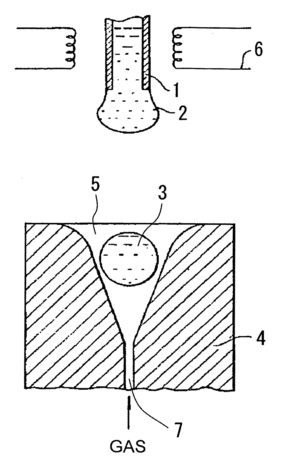
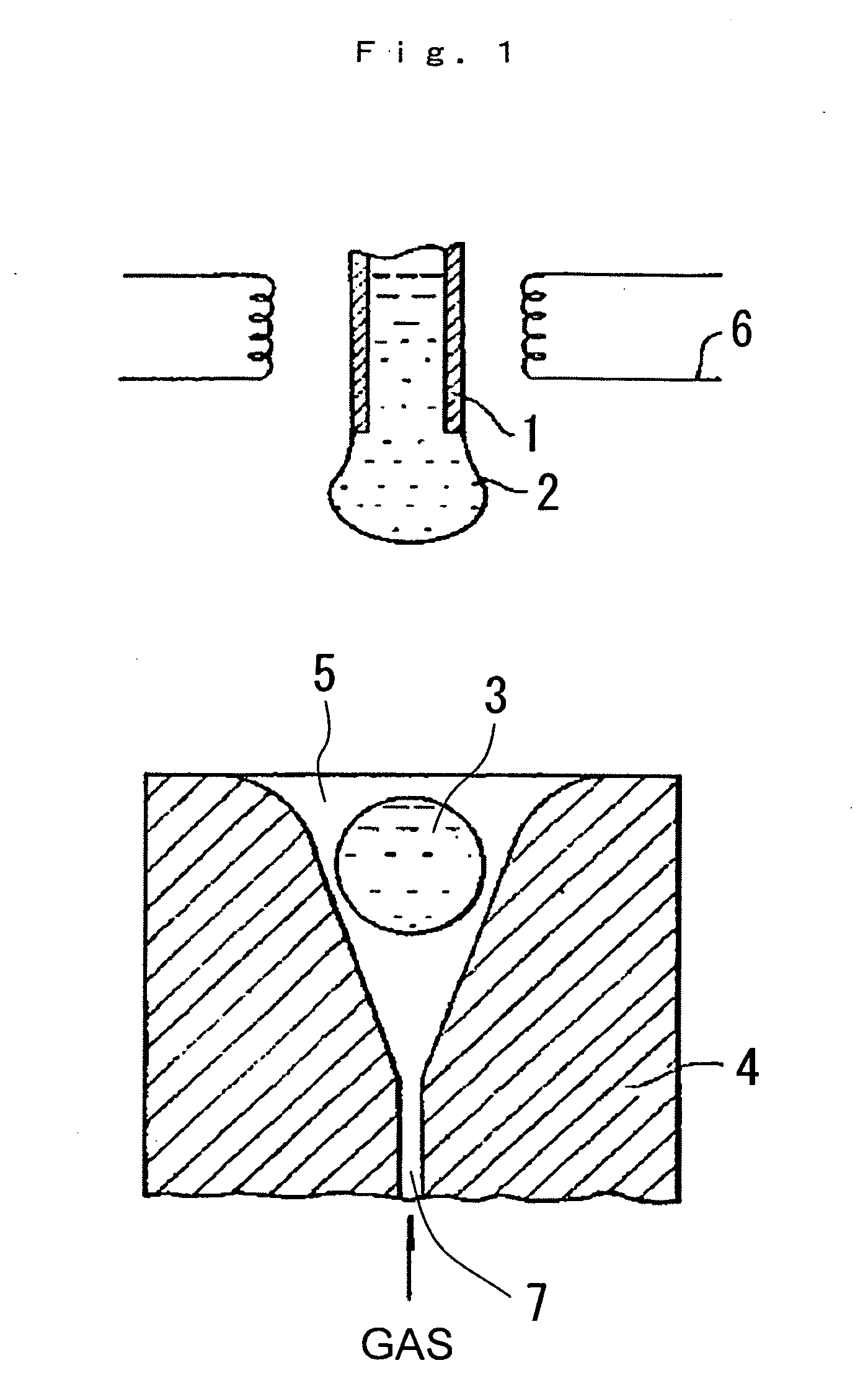
[0080] The device shown in FIG. 1 was employed in the manufacturing of the crude glass spheres. An examination of the dripped and formed crude glass spheres following cooling revealed striae within 90 micrometers of the surface. Because lanthanum borate glass was employed, these were attributed to marked volatilization from the glass surface during dripping and forming. Continuous and stable forming under conditions capable of suppressing surface striae was not readily achieve...


PUM

PropertyMeasurementUnit
Lengthaaaaaaaaaa
Lengthaaaaaaaaaa
Viscosityaaaaaaaaaa

Abstract

A method of manufacturing a precision glass sphere employed as a glass material (preform) in the molding of optical elements such as lenses, where the precision glass sphere that has been preformed with good weight precision and has an outer surface free of optically nonuniform layers. A method of manufacturing optical glass elements employing this precision glass sphere.

Description

FIELD OF THE INVENTION [0001] The present invention relates to a method of manufacturing a precision glass sphere employed as a glass material (preform) in the molding of optical elements such as lenses, where the precision glass sphere that has been preformed with good weight precision and has an outer surface free of optically nonuniform layers. The present invention further relates to a method of manufacturing optical glass elements employing this precision glass sphere. BACKGROUND OF THE INVENTION [0002] The method of press molding a glass material in a pressing mold that has been precision processed based on the final shape of a desired optical element (referred to as “precision press molding” hereinafter) to obtain an optical glass element such as a lens is known. This method is highly advantageous for manufacturing optical elements having aspherical surfaces, optical elements having minute patterns, and other optical elements that are difficult to form simply by grinding and ...

Claims


Application Information

Patent Timeline
IPC IPC(8): C03B7/12C03B11/00C03B11/08C03B19/10C03B40/04C03C12/00C03C19/00
CPCC03B7/12C03C12/00C03B40/04C03B11/08A63C17/04A63C17/1409
Inventor YAMASHITA, TERUOHAYASHI, SHIGERUYOSHIDA, MASAHIRO
Owner HOYA CORP
Learn More