Suppression method of radionuclide deposition on reactor component of nuclear power plant and ferrite film formation apparatus

Active Publication Date: 2007-06-07
HITACHI-GE NUCLEAR ENERGY LTD
View PDF4 Cites 7 Cited by
  • Summary
  • Abstract
  • Description
  • Claims
  • Application Information

AI Technical Summary

Benefits of technology

[0011] It is an object of the present invention to efficiently suppress

Problems solved by technology

However, the presence of metallic impurities in reactor water is unavoidable, and one part of these impurities will be deposited in the form of metal oxides on the fuel rod surfaces.
However, the unremoved ones will be deposited on the portions where the recycling system component contacts with the reactor water while the reactor water is circulating in the systems, e.g. recycling system.
As a result, the radioactive ray may b

Method used


Image

  • Suppression method of radionuclide deposition on reactor component of nuclear power plant and ferrite film formation apparatus
  • Suppression method of radionuclide deposition on reactor component of nuclear power plant and ferrite film formation apparatus
  • Suppression method of radionuclide deposition on reactor component of nuclear power plant and ferrite film formation apparatus

Examples


example 1

[0128]FIG. 6 illustrates an overall nuclear power plant structure, in which the ferrite film formation apparatus of the present invention is connected to the reactor water recycling line, and FIG. 7 illustrates the detailed ferrite film formation apparatus structure.

[0129]FIG. 6 illustrates the case in which the ferrite film formation apparatus 30 of the present invention is provided in a reactor water recycling line system. As illustrated in FIG. 6, the nuclear power plant has a structure with the nuclear reactor 1 which contains fuel rods in a pressure vessel, a main steam line 2 connected to the reactor 1, a steam turbine power generator 3 connected to the main steam line 2, and condenser connected to the steam turbine power generator 3 at the steam exhaust port. The condensate formed in a condenser 4 is drained by a condensate pump 5 to be recycled back as supplied water to the reactor 1 by a water supply piping system 10 provided with a condensate cleaning unit 6, a water supp...

example 2

[0167]FIG. 10 illustrates a system schematic with 2 recycling lines 22.

[0168] The ferrite film formation apparatus 30 is basically the same as that shown in FIGS. 8 and 7, except that a valve for switching the flow path is added so that the treatment solution can flow in both recycling lines 22.

[0169] This system has basically the same work flow with respect to the chemical decontamination and the formation of the ferrite film as that shown in FIG. 1, except that the treatment solution is alternately transferred to the 2 recycling lines 22 (hereinafter “Line A” and “Line B”, respectively) in the following manner so that these lines can be simultaneously treated for the formation of the ferrite film.

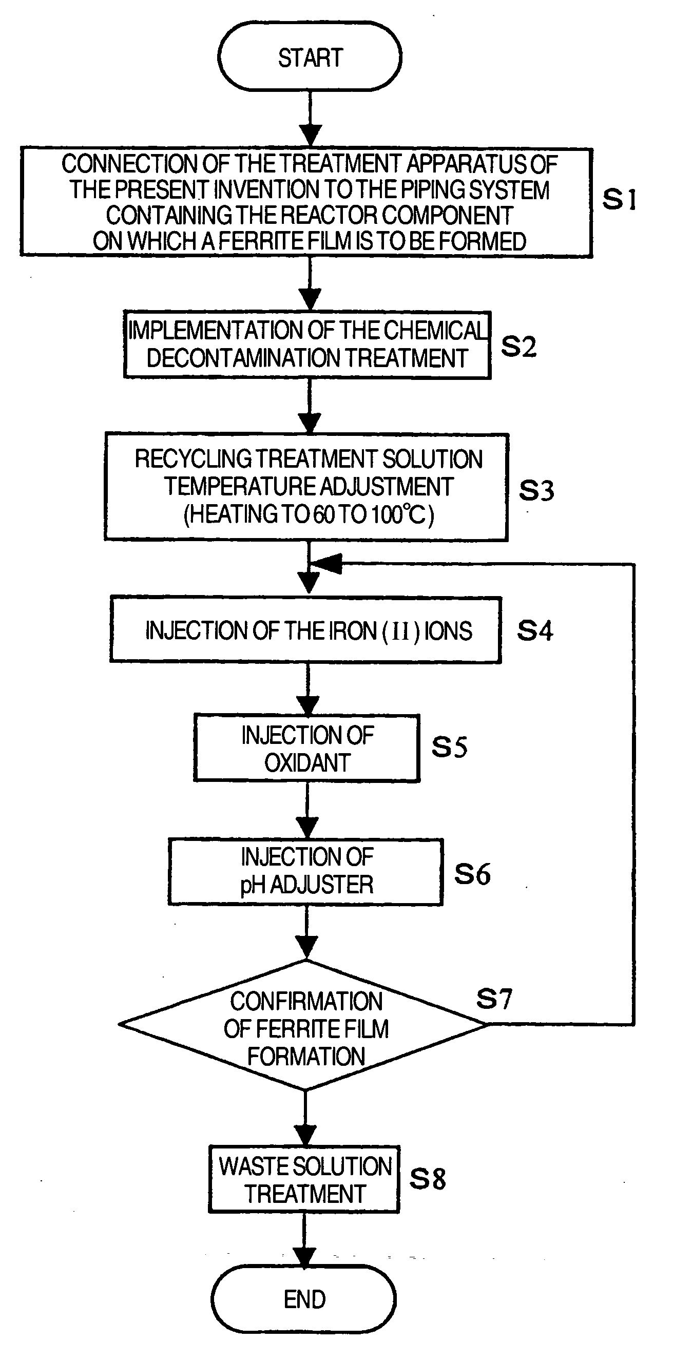
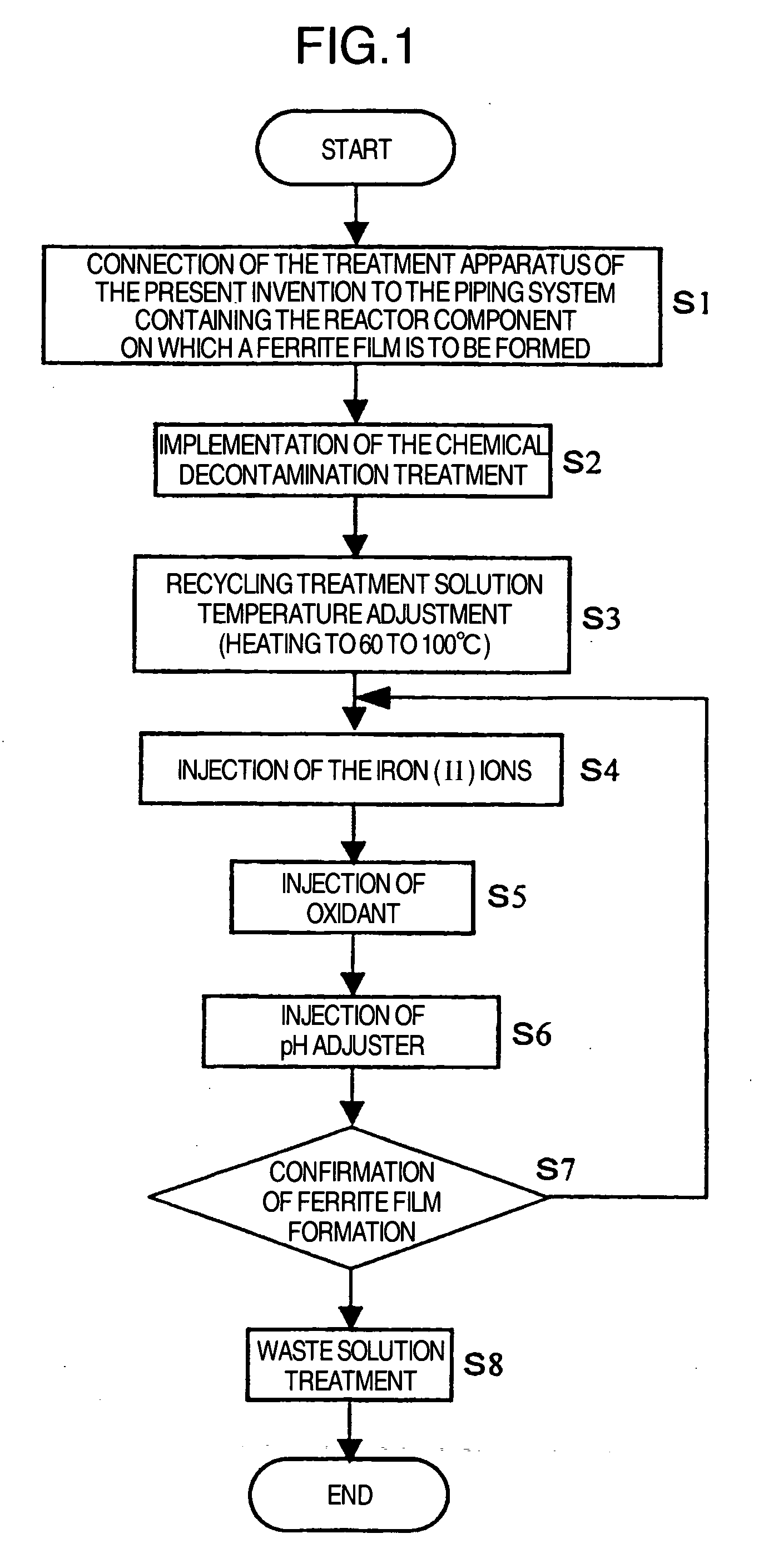
[0170] In the apparatus of Example 1 (see FIG. 8), the ferrite film formation apparatus 30 and recycling line 22 are connected to each other by 2 lines. In the system of Example 2 (see FIG. 10), on the other hand, the ferrite film formation apparatus 30 is connected, by one line, to ea...

example 3

[0175]FIG. 11 illustrates a system schematic of Example 3. The system of the embodiment of Example 3 has basically the same devices and their arrangement as that of the embodiment of Example 1 illustrated in FIG. 7, except that it has the bubbling unit 71 for bubbling the treatment solution in the surge tank 31 and the first agent in the agent tank 45 with an inert gas (e.g. nitrogen).

[0176] Bubbling the first agent and the treatment solution in the surge tank with an inert gas removes the dissolved oxygen from each solution, thereby making them essentially oxygen-free. This accelerates the ferrite film forming reactions by suppressing formation of the iron (III) ions in each solution which has no contribution to ferrite film formation.


PUM

PropertyMeasurementUnit
Temperatureaaaaaaaaaa

Abstract

It is an object of the present invention to efficiently suppress radionuclide deposition on a reactor component of nuclear power plant. Radionuclide deposition on the surface of a metallic reactor component of nuclear power plant is suppressed by forming a ferrite film on the component, wherein the film is formed, after decontamination for removing radionuclides contaminants from the component surface is completed and before the plant is started up, by contacting a treatment solution which mixes a first agent containing the iron (II) ions, a second agent for oxidizing the iron (II) ions into the iron (III) ions and a third agent for adjusting pH level of a solution to 5.5 to 9.0 in this order with the reactor component surface.

Description

FIELD OF THE INVENTION [0001] The present invention relates to a suppression method of radionuclide deposition on a reactor component of nuclear plant, e.g. power plant, and ferrite film formation apparatus therefor. BACKGROUND OF THE INVENTION [0002] A boiling reactor water (hereinafter referred to as BWR) type nuclear power plant compulsorily circulates cooling water by a recycling pump or an internal pump in the reactor which contains fuel rods in a pressure vessel in order to efficiently transfer heat generated in fuels to cooling water. The cooling water vapor generated in the reactor is mostly used to drive a steam turbine for power generation. The vapor which is discharged from the turbine is condensed by a condenser, and the condensate is almost completely degassed to be recycled back to the reactor as cooling water. The almost completely degassing removes oxygen and hydrogen produced by radiolysis of water in the reactor core. The condensate is treated, before being recycle...

Claims


Application Information

Patent Timeline
IPC IPC(8): G21C3/00
CPCC23F15/00G21C13/087G21C19/00G21Y2002/201G21Y2004/40Y02E30/40Y02E30/30
Inventor HOSOKAWA, HIDEYUKINAGASE, MAKOTOISHIDA, KAZUSHIGEWADA, YOUICHIUSUI, NAOSHIAIZAWA, MOTOHIROFUSE, MOTOMASA
Owner HITACHI-GE NUCLEAR ENERGY LTD
Why Eureka
Try Eureka