Electroplated abrasive tools, methods, and molds

a technology of abrasive tools and molds, which is applied in the direction of gear teeth, grinding devices, gear teeth, etc., can solve the problems of hammering the performance and usable life of many known superabrasive tools, the height to which a superabrasive particle extends above the tool substrate, and the placement and retention of superabrasive particles remain problemati

Inactive Publication Date: 2007-06-07
SUNG CHIEN MIN
View PDF17 Cites 41 Cited by
  • Summary
  • Abstract
  • Description
  • Claims
  • Application Information

AI Technical Summary

Problems solved by technology

Despite their apparent advantages, a number of issues continue to hamper the performance and usable life of many known superabrasive tools.
For example, superabrasive particle placement and retention remain problematic.
One add

Method used


Image

  • Electroplated abrasive tools, methods, and molds
  • Electroplated abrasive tools, methods, and molds
  • Electroplated abrasive tools, methods, and molds

Examples


example 1

Manufacture of a CMP Pad Dresser

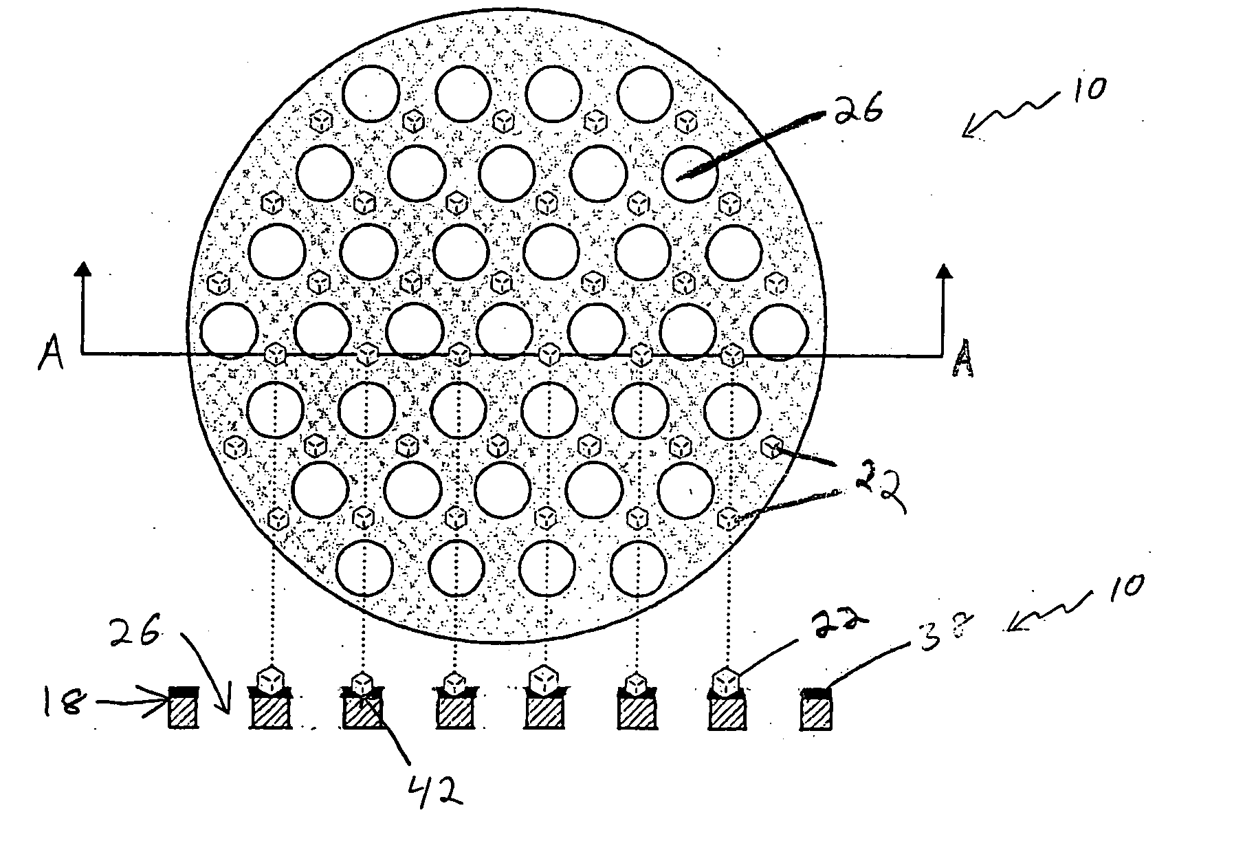
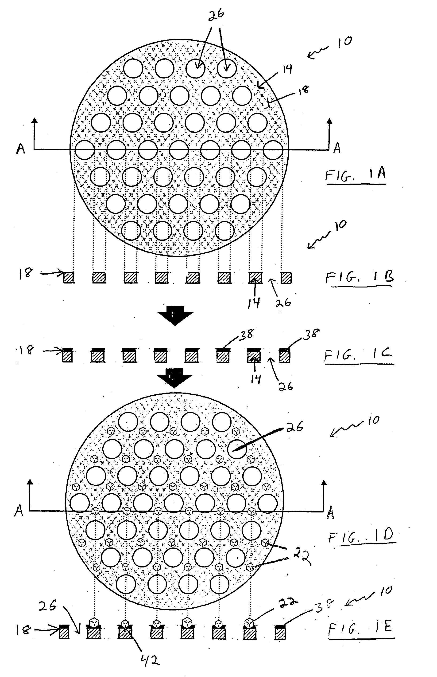
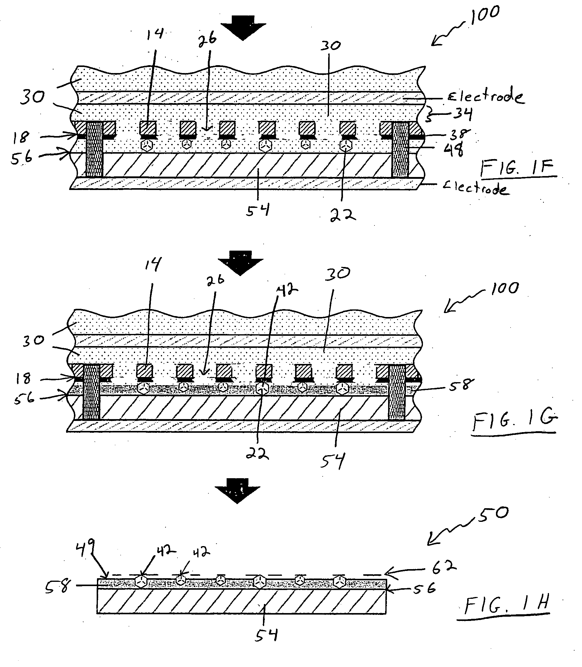
[0069] A mold of a polyimide layer (1 mm thick) that is stamped to contain a plurality of apertures arranged in a lattice pattern. The center of each aperture is separated from the center of neighboring apertures by a distance of 0.7 mm, and each aperture has a 0.5 mm diameter. One surface of the polyimide layer (i.e. the molding surface) is coated with an acrylic adhesive (50 microns thick). Diamond grits of 100 / 120 mesh are attached to the molding surface with each diamond grit located in the center of the four surrounding apertures. The diamond covered molding surface is placed against a disc-shaped stainless steel substrate (being 108 mm in diameter by 6.5 mm in thickness). The diamond grits are between the molding surface and the stainless steel substrate. The mold and the substrate are located in a plastic (PVC) ring 48 to hold them together during electrolytic process. The substrate is placed in contact with a cathode. NiSO4 solution is used a...

example 2

[0070] Thirty molds are made as follows:

[0071] Each mold is formed of a stainless steel disc that is about 120 mm in diameter and about 120 microns in thickness. Each disc is lithographically etched to form a plurality of apertures thereon distributed in a lattice pattern as described below. The apertures cover a generally circular area on a central portion of each disc of about 100 mm in diameter, leaving a width of about 20 mm around the perimeter of each disc without any apertures. Measuring from the approximate center points of adjacent apertures, (the “aperture separation”), a number of discs are formed with the following aperture separations:

[0072] 1. Ten discs with an aperture separation of about 800 microns, each aperture about 400 microns in diameter;

[0073] 2. Ten discs with an aperture separation of 600 microns, each aperture about 300 microns in diameter;

[0074] 3. Ten discs with an aperture separation of 400 microns, each aperture about 200 microns in diameter.

[0075]...


PUM


Abstract

The present invention provides for a mold that can position and hold abrasive particles, which are to be electrolytically attached to an electrically conductive substrate during an electrolytic process. The mold can include an insulating material with a molding surface suitable for holding the abrasive particles in place during this process. Additionally, a method for making an abrasive tool using such a mold is provided, as well as abrasive tools made thereby. In one aspect of this invention, abrasive tools can have abrasive particle tips that are arranged in accordance with a predetermined vertical pattern and/or a predetermined horizontal pattern in a manner that requires little or no post electrodeposition processing.

Description

FIELD OF THE INVENTION [0001] The present invention relates generally to electroplated abrasive tools and methods and molds for making electroplated abrasive tools. Accordingly, the present invention involves the fields of electrochemistry, materials science, and physics. BACKGROUND OF THE INVENTION [0002] Abrasive tools have long been used in numerous applications, including the cutting, drilling, sawing, grinding, lapping, and polishing of materials. One common form of an abrasive tool is one that uses abrasive particles on a tool substrate to perform the cutting, grinding, polishing, etc. [0003] Superabrasive particles, such as diamond, polycrystalline diamond (PCD), cubic boron nitride (CBN), and polycrystalline cubic boron nitride (PCBN) have been widely used for many materials removal applications due to their extreme hardness, atomic density, and high thermal conductivity. For example, dressing disks, grinding disks, saw blades, wire saws, and drill bits have all included sup...

Claims


Application Information

Patent Timeline
IPC IPC(8): B24B7/16
CPCB24D18/0009B24D18/0018
Inventor SUNG, CHIEN-MIN
Owner SUNG CHIEN MIN
Why Eureka
Try Eureka