Data storage device, information transmitter, data storage system and information processing system

a data storage device and information transmitter technology, applied in the field of data storage devices, can solve the problems of limiting the number of operation buttons, difficult for users to freely set the file name and folder name of each data file to be stored in the memory,

Inactive Publication Date: 2007-06-07
SHARP KK
View PDF8 Cites 20 Cited by
  • Summary
  • Abstract
  • Description
  • Claims
  • Application Information

AI Technical Summary

Problems solved by technology

Along with this tendency, there is a limit in the number of operation buttons, and therefore frequently it becomes difficult for a user to freely set a file name and a folder name of each data file to be stored in the memory.

Method used


Image

  • Data storage device, information transmitter, data storage system and information processing system
  • Data storage device, information transmitter, data storage system and information processing system
  • Data storage device, information transmitter, data storage system and information processing system

Examples


embodiment 1

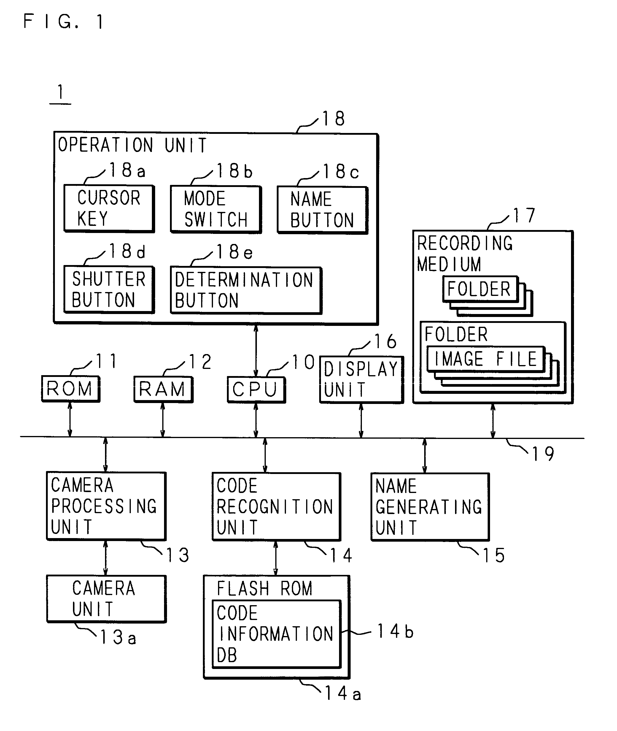
[0093] A data storage device according to the present invention will be explained in detail hereunder, based on the drawings showing a digital camera as an embodiment 1 thereof. FIG. 1 is a block diagram showing an exemplary constitution of the digital camera as the data storage device according to the present invention. A designation mark “1” in the figure indicates the digital camera as the data storage device according to the present invention, and the digital camera 1 comprises a CPU (Central Processing Unit) 10, a ROM 11, a RAM 12, a camera processing unit 13, a code recognition unit 14, a name generation unit 15, a display unit 16, and a recording medium 17, etc, each being mutually connected via a bus 19.

[0094] The CPU 10 functions as a control center of the digital camera 1 and controls each part of the aforementioned hardware mutually connected via a bus 19, and also realizes various software-based functions, following control programs previously stored in the ROM 11. The ...

embodiment 2

[0134] The data storage system according to the present invention will be explained in detail hereunder, based on the drawings showing the embodiment 2. FIG. 7 is a block diagram showing an exemplary constitution of the digital camera in the data storage system according to the present invention, and FIG. 8 is a block diagram showing an exemplary constitution of the recording and reproducing apparatus in the data storage system according to the present invention.

[0135] The data storage system of this embodiment 2 is composed of a digital camera 2 as the information transmitter of the present invention, and a recording and reproducing apparatus 3 as the data storage device of the present invention. A wireless communication following IrDA (Infrared Data Association) standard using infrared rays is possible between the digital camera 2 and the recording and reproducing apparatus 3. Note that not only the wireless communication using the infrared rays, but also the wireless communicati...

embodiment 3

[0172] The information processing system according to the present invention will be explained in detail hereunder, based on the drawings showing an embodiment 3. The information processing system of this embodiment 3 is composed of the digital camera 2 (see FIG. 7) as the information transmitter of the present invention, and the recording and reproducing apparatus 3 (see FIG. 8) as the information processor of the present invention. The information processing system of the present invention can be realized by the same structure as that of the above-described data storage system of the embodiment 2, and is composed of the digital camera 2 and the recording and reproducing apparatus 3 of the embodiment 2, and therefore the explanation is omitted.

[0173] In the information processing system of this embodiment 3, the recording and reproducing apparatus 3 records in the DVD recorder 36 each broadcast program received by the tuner 35 as the image file. In addition, the recording and repro...


PUM

PropertyMeasurementUnit
hierarchical structureaaaaaaaaaa
timeaaaaaaaaaa
distanceaaaaaaaaaa

Abstract

To provide a data storage device and a data storage system capable of giving an arbitrary name to a folder and a file in each data to be stored in a memory. For example, pieces of code information are corresponded to respective two-dimensional bar codes and stored in a code information DB 14b, and a code recognition unit 14 recognizes a code stored in the code information DB 14b from image data obtained by picking up an image by a camera unit 13a, and a piece of the code information corresponding to the recognized code is extracted from the code information DB 14b. In addition, based on the extracted piece of the code information, a name generation unit 15 generates a folder name or a file of an image file stored in a recording medium 17.

Description

[0001] This application is national phase under 35 U.S.C. §371 of PCT International Application No. PCT / JP2004 / 009107 which has an international filing date of Jun. 28, 2004, and designated the United States of AmericaTECHNICAL FIELD [0002] The present invention relates to a data storage device that stores acquired data in a hierarchical structure. In particular, the present invention relates to the data storage device, with an image pickup unit provided therein, that generates names of a file of the data and a folder having each file based on code information in image data obtained by picking up an image at the image pickup unit. The present invention also relates to, with the image pickup unit provided therein, an information transmitter that analyzes a code extracted from the image data obtained by picking up the image at the image pickup unit and transmits code information thus obtained to outside, a data storage system that generates a folder name or a file name of the data sto...

Claims


Application Information

Patent Timeline
Patent Type & Authority Applications(United States)
IPC IPC(8): G06F7/00G06F12/00G06K17/00G11B27/10G11B27/11G11B27/32G11B27/34H04N5/225H04N5/76H04N5/765H04N5/77H04N5/781H04N5/85H04N5/907H04N5/91H04N9/804H04N9/82
CPCG06F17/30011G11B27/105G11B27/11G11B27/329G11B27/34G11B2220/2562H04N9/8205H04N5/765H04N5/772H04N5/781H04N5/85H04N5/907H04N9/8047G11B2220/65G06F16/93
Inventor YOSHIKAWA, TADASHI
Owner SHARP KK
Why Eureka
Try Eureka