

Inertial sensor
a sensor and sensor technology, applied in the direction of turning-sensitive devices, acceleration measurement using interia forces, instruments, etc., can solve the problems of unstable detection sensitivity, affecting the accuracy of the detection value of angular rate, and affecting the accuracy of the detection value, so as to reduce the reliability, the amplitude and vibration velocity of the mass, and the detection sensitivity. stability is likely to increase.
- Summary
- Abstract
- Description
- Claims
- Application Information
AI Technical Summary
Benefits of technology
Problems solved by technology
Method used
Image

Examples
embodiment 1
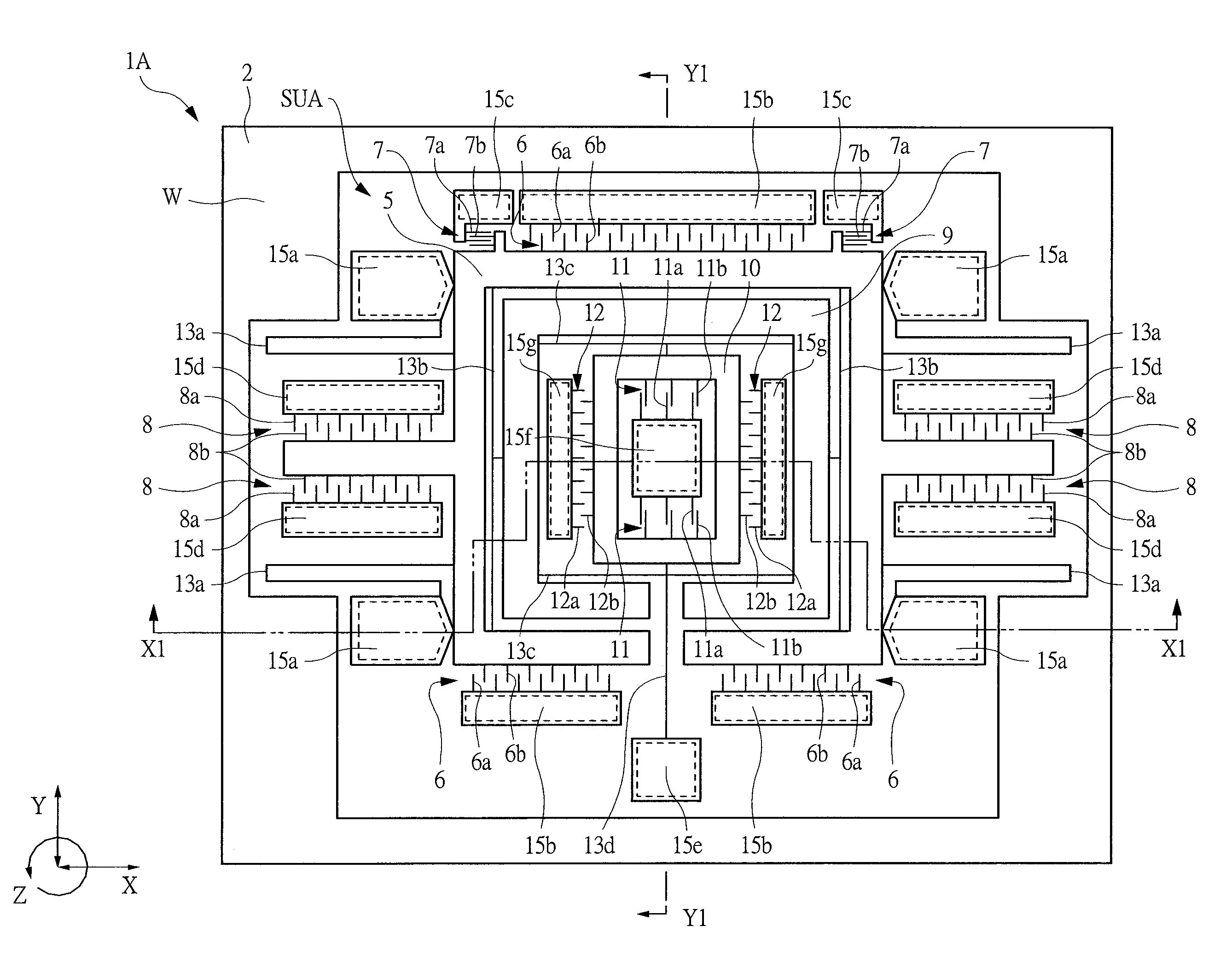
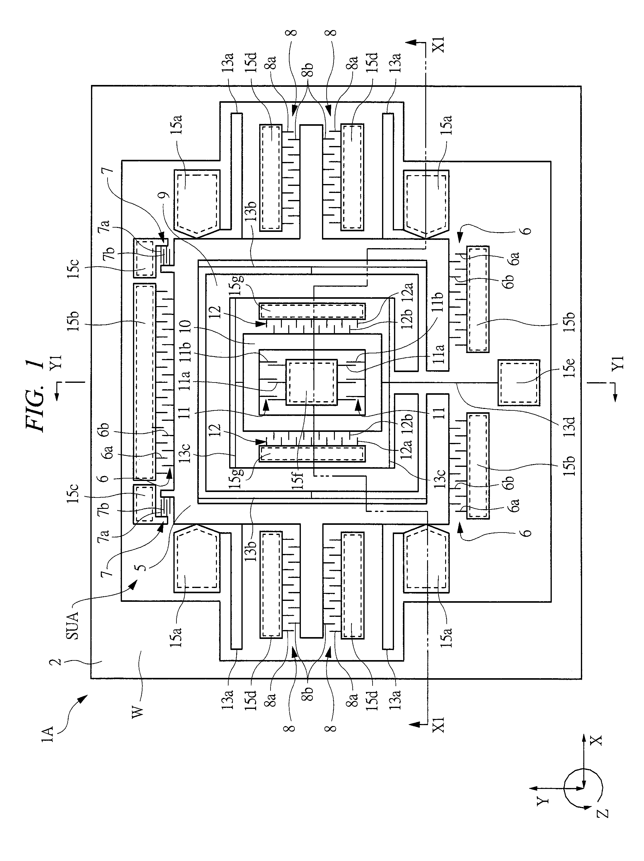
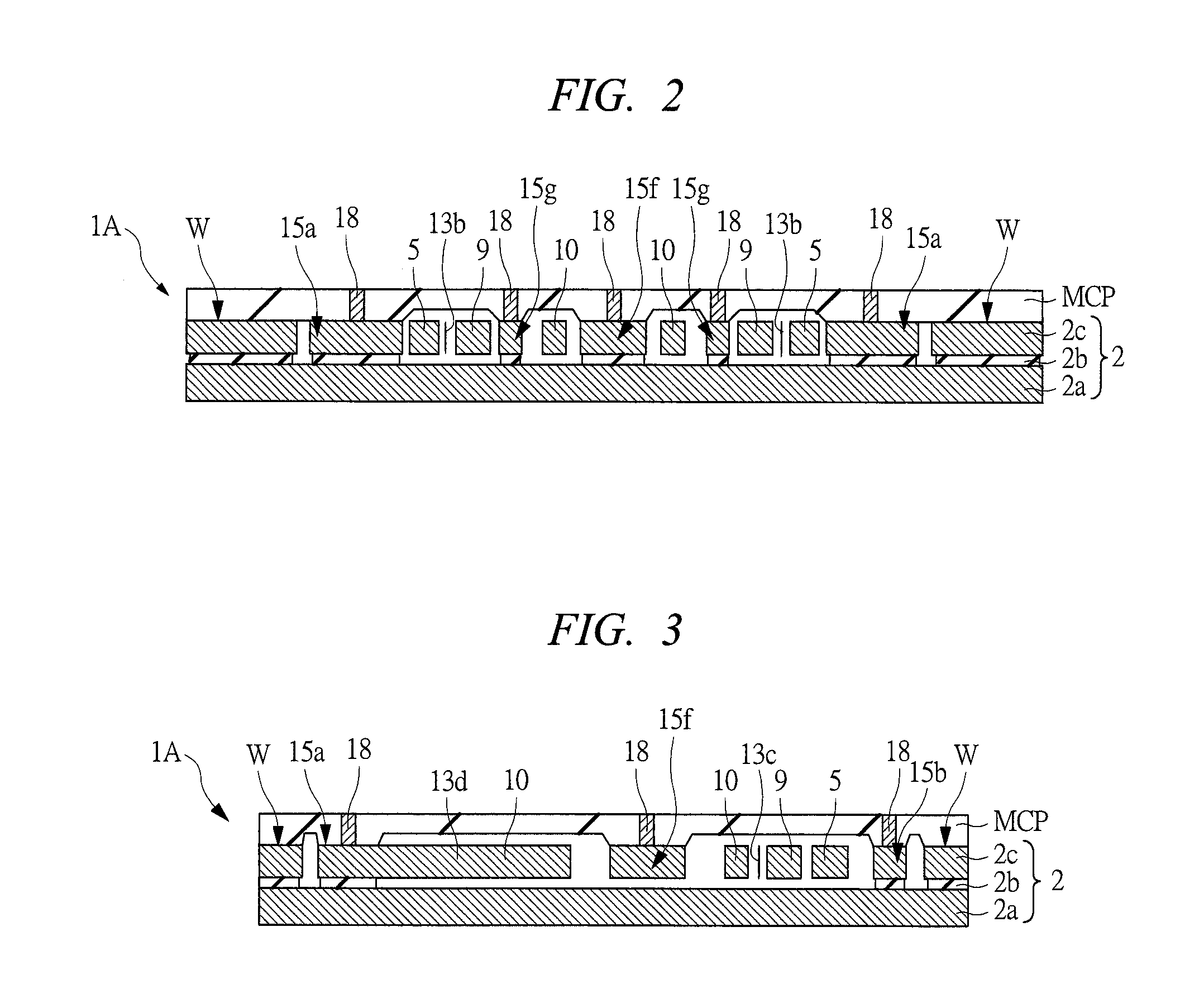
[0042]FIG. 1 is a plan view showing one example of an inertial sensor according to a first preferred embodiment of the present invention. FIG. 2 is a sectional view taken along line X1-X1 shown in FIG. 1. FIG. 3 is a sectional view taken along line Y1-Y1 shown in FIG. 1. FIG. 4 is a block diagram showing the inertial sensor of FIG. 1 in schematically simplified manner. FIG. 5 is a circuit diagram of a drive circuit of the inertial sensor of FIG. 1. FIG. 6 is a circuit diagram of a detection circuit in the inertial sensor of FIG. 1. Further, to facilitate visualization of the drawing, FIG. 1 is shown without a sealing cap. Moreover, a reference symbol Y indicates a first direction, and a reference symbol X indicates a second direction X orthogonal to the above-mentioned first direction Y.
[0043] An inertial sensor 1A according the first embodiment is a sensor to measure physical value to arise due to inertia of object such as acceleration, angular rate (gyro), and angle. According to...
embodiment 2
[0092] In a second embodiment, an example in which a Coriolis frame and a detection frame of above-mentioned inertial sensor are formed in an integral structure is described. FIG. 7 shows a plan view of one example of an inertial sensor 1B according to the second embodiment. In FIG. 7, to facilitate visualization of the drawing, illustration of a sealing cap is omitted.
[0093] In the second embodiment, inside a drive frame 5 of a sensor unit SUB, an element 20 is disposed between the drive frame 5 and a support 15f. The element 20 is an integral structure of a Coriolis frame 9 and a detection frame 10 as mentioned above, and functions as both a Coriolis frame 9 and a detection frame 10. This element 20 is formed by an active layer 2c thereof being patterned to be frame-like in planar shape. This element 20, with the insulating layer 2c being an under-layer thereof removed, is disposed in the suspended state over the first principal plane of a basement layer 2.
[0094] Furthermore, th...
embodiment 3
[0099] In a third embodiment, a construction of an inertial sensor is the same as those of the first and second embodiments. A different point is that functions of a drive frame 5 and a detection frame 10 of FIG. 1 are opposite to the construction of the inertial sensor 1A of the first embodiment. Furthermore, in the inertial sensor 1B of the second embodiment, the element 20 in FIG. 7 functions as both a drive frame and a Coriolis frame described in the first embodiment, the drive frame 5 in FIG. 7 functions as a detection frame described in the first embodiment.
[0100] Functions of each component of the inertial sensor according to the third embodiment will be described using FIG. 1 used in the description of the first embodiment as follows.
[0101] In the third embodiment, a detection frame 10 is displaced in the driving direction (herein, the second direction X) by servo means 12. Further, a drive frame 5 is displaced in the detection direction (herein, the first direction Y), an...
PUM
 Abstract
Description
Claims
Application Information