Single-ended barrel engine with double-ended, double roller pistons

a single-barrel, double-rolling technology, applied in the direction of machines/engines, positive displacement liquid engines, mechanical equipment, etc., can solve the problems of lack of long-term durability, cumbersome and complex design of the pivoting head of the saab, and the ability of the variable compression ratio engine has not been used in commercial applications, so as to reduce the side load of the piston, optimize the ability of the piston motion, and simplify the variable compression ratio

Inactive Publication Date: 2007-06-14
THOMAS ENGINE CO LLC
View PDF17 Cites 0 Cited by
  • Summary
  • Abstract
  • Description
  • Claims
  • Application Information

AI Technical Summary

Benefits of technology

[0012] The present invention provides improvements to barrel engines by mating the simplified variable compression ratio and optimized piston motion abilities of a single-ended barrel engine with a rigid and durable crosshead piston design. A unique double-ended, double roller piston is employed that uses one end for combustion and the other end as a crosshead guide means to reduce side loading on the piston. In some embodiments, the barrel engine includes a variable compression ratio device, while in other embodiments it includes an integral supercharger. In still other embodiments, the engine includes a non-sinusoidal cam surface, which causes the combustion ends of the pistons to move non-sinusoidally. In some embodiments, these features are used in combination with one another.
[0014] In one alternative embodiment, the guide end of the piston is a pumping end and the guide cylinder is a pumping cylinder with a closed outer end. The pumping end and the pumping cylinder cooperate to compress a gas. The engine further includes a valve assembly for providing the gas to the pumping cylinder and venting compressed gas from the pumping cylinder. A compressed gas conduit is in fluid communication with the valve assembly and the intake system such that the compressed gas from the pumping cylinder is provided to the combustion chamber so as to supercharge the engine.

Problems solved by technology

In spite of their benefit and applications, engines with variable compression ratio abilities have not been used in commercial applications due to issues of extreme complexity, lack of long-term durability and prohibitively high costs.
In spite of its benefits, Saab's pivoting head design is cumbersome and complex, has potential sealing issues and is prohibitively expensive.
Other attempts to vary compression ratio in conventional slider-crank engines are generally inferior to the Saab technique for various reasons.
However, the usefulness of variable valve timing for other variable compression ratio applications is very limited.
This results in significant penalties in the effective displacement of the engine as compression ratio is lowered.
A reduction in the effective engine displacement at this time significantly reduces the peak power capability of the engine and usually offsets any benefits that can be gained by a varying compression ratio.
This level of optimized piston motion is not possible in slider-crank engines, which are restricted to sinusoidal piston motion or in double-ended barrel engines, which cannot independently optimize piston motion for each cycle.
While single-ended barrel engines provide a simple and inexpensive means of varying compression ratio and the ability independently optimize piston motion for various engine cycles, prior art single-ended barrel engines with these abilities have yet to demonstrate a piston structure that is both structurally and kinematically feasible at normal engine speeds.
Prior art single-ended barrel engines employ single-ended or double-ended, single roller piston designs that lack critical crosshead and roller support qualities needed for a feasible design.

Method used


Image

  • Single-ended barrel engine with double-ended, double roller pistons
  • Single-ended barrel engine with double-ended, double roller pistons
  • Single-ended barrel engine with double-ended, double roller pistons

Examples


Embodiment Construction

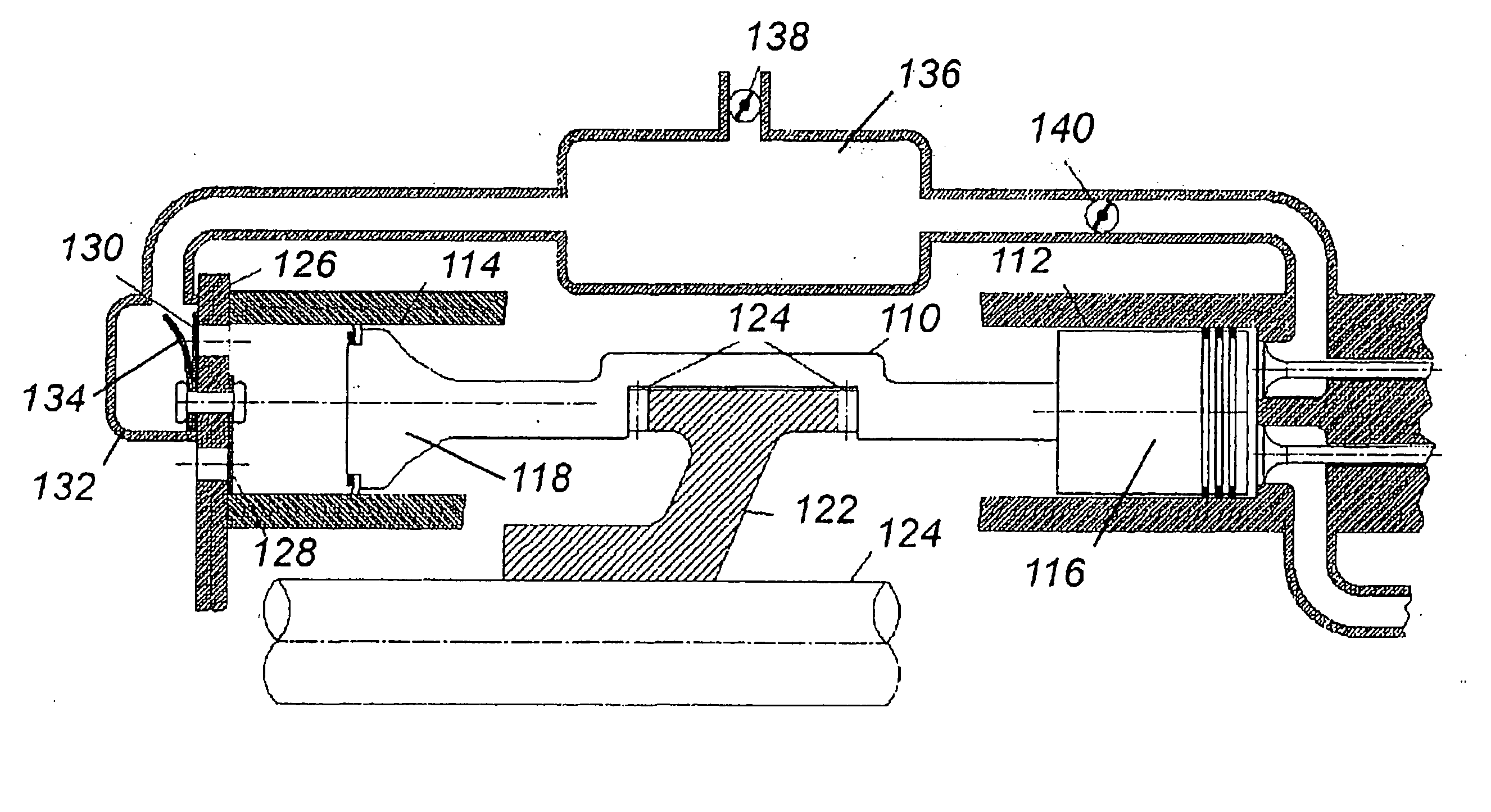
[0027] A single-ended barrel engine design presents a unique opportunity to vary compression ratio by simple and inexpensive means, and to optimize piston motion. A single-ended barrel engine is one that contains only one central track for driving piston motion, with the combustion event occurring on only one side of the track and one end of the engine. This configuration is less complicated than opposing piston and double-ended barrel engine designs and provides an engine structure that allows the engine's compression ratio to be easily and simply varied by axially changing the position of the track. A single-ended barrel engine design also allows piston motion to be independently optimized for the intake, compression, combustion and exhaust cycles because power is produced on only one side of the track. FIG. 1 illustrates an example of a single-ended barrel engine.

[0028] The engine 10 in FIG. 1 is merely representative of the general configuration of an engine referred to herein ...


PUM

PropertyMeasurementUnit
compression ratioaaaaaaaaaa
constant distanceaaaaaaaaaa
diameteraaaaaaaaaa

Abstract

An internal combustion barrel engine includes an engine housing with a first and second end. An elongated power shaft is longitudinally disposed in the engine housing and defines a longitudinal axis. A combustion cylinder and a guide cylinder are spaced apart and disposed on a common cylinder axis that is generally parallel to the central axis. The cylinders each have an inner end and an outer end, with the inner ends being closer to each other. The outer end of the combustion cylinder is closed. An intake system is operable to introduce a mixture of air and / or fuel into the combustion cylinder. A track is supported between the inner ends of the cylinders and has an undulating cam surface. The track is moveable such that the portion of the cam surface most directly between the cylinders undulates toward and away from the inner end of the combustion cylinder. A double-ended piston includes a combustion end disposed in the combustion cylinder so as to define a combustion chamber between the combustion end and the closed end of the combustion cylinder. A guide end is disposed in the guide cylinder. A midportion extends between the combustion end and the guide end and is in mechanical communication with the guide surface of the track. A variable compression ratio device is operable to move the track axially towards and away from the inner end of the combustion cylinder so as to adjust the compression ratio. Combustion occurs only in the combustion cylinder and does not occur in the guide cylinder.

Description

CROSS-REFERENCE TO RELATED APPLICATIONS [0001] This application is a continuation-in-part of the following patent applications: U.S. patent application Ser. No. 10 / 021,192, filed Oct. 30, 2001, and U.S. patent application Ser. No. 10 / 263,264, filed Oct. 2, 2002. This application also claims priority from U.S. Provisional Patent Applications Ser. Nos. 60 / 377,011, filed Apr. 30, 2002; 60 / 377,072, filed Apr. 30, 2002; 60 / 377,053, filed Apr. 30, 2002; and 60 / 376,638, filed Apr. 30, 2002. [0002] U.S. patent application Ser. No. 10 / 021,192, in turn, claims priority from U.S. Provisional Patent Application Ser. Nos. 60 / 244,349, filed Oct. 30, 2000; 60 / 252,280, filed Nov. 21, 2000; 60 / 260,256, filed Jan. 8, 2001; 60 / 261,060, filed Jan. 11, 2001; and 60 / 267,958, filed Feb. 9, 2001; and is a continuation-in-part of U.S. patent application Ser. No. 09 / 937,543, filed Sep. 26, 2001, which is a U.S. National Phase of PCT / US00 / 07743, filed Mar. 22, 2000, which claims priority from U.S. Provisional...

Claims


Application Information

Patent Timeline
Patent Type & Authority Applications(United States)
IPC IPC(8): F02B75/04F02B75/22F01B3/00F01B3/04F02B1/12F02B3/06F02B41/04F02B47/02F02B51/04F02B57/08F02B75/02F02B75/26F02B75/36F02F7/00F04B39/10F04B41/04
CPCF01B3/0005F01B3/0035F01B3/0085F01B3/04F02B1/12F02B3/06F02B41/04F02B47/02F02B51/04F02B57/08F02B75/02F02B75/04F02B75/26F02B75/36F02B2075/025F02B2075/027F02F7/0087F04B39/1073F04B41/04F05C2253/16Y02T10/121Y02T10/126Y02T10/12
Inventor THOMAS, CHARLES RUSSELLHAUSER, BRET R.BRANYON, DAVID P.
Owner THOMAS ENGINE CO LLC
Why Eureka
Try Eureka