Reservoir apparatus for a bicycle brake lever device

a technology of hydraulic apparatus and brake lever, which is applied in the field of bicycles, can solve problems such as degrading braking performan

Active Publication Date: 2007-06-14
SHIMANO INC
View PDF25 Cites 16 Cited by
  • Summary
  • Abstract
  • Description
  • Claims
  • Application Information

AI Technical Summary

Benefits of technology

[0005] The present invention is directed to various features of a bicycle brake device. In one embodiment, a reservoir apparatus for a bicycle brake lever device comprises a master cylinder and a fluid reservoir including first and second reservoirs. The master cylinder has a master cylinder chamber dimensioned for receiving a master cylinder piston therein. The first reservoir has a first reservoir chamber in fluid communication with the master cylinder chamber for supplying a hydraulic fluid to the master cylinder chamber. At least a portion of the first reservoir chamber is disposed below a portion of the master cylinder chamber. The second reservoir has a second reservoir chamber in fluid communication with the first reservoir chamber, wherein the second reservoir chamber includes an air entrainment surface. The air entrainment surface is positioned higher than an upper surface of the first reservoir chamber. Additional inventive features will become apparent from the description below, and such features alone or in combination with the above features may form the basis of further inventions as recited in the claims and their equivalents.

Problems solved by technology

However, sometimes entrained air in the fluid reservoir may enter the master cylinder and be introduced into the path from the piston in the brake lever assembly to the piston(s) in the caliper, thereby degrading braking performance.

Method used


Image

  • Reservoir apparatus for a bicycle brake lever device
  • Reservoir apparatus for a bicycle brake lever device
  • Reservoir apparatus for a bicycle brake lever device

Examples


Embodiment Construction

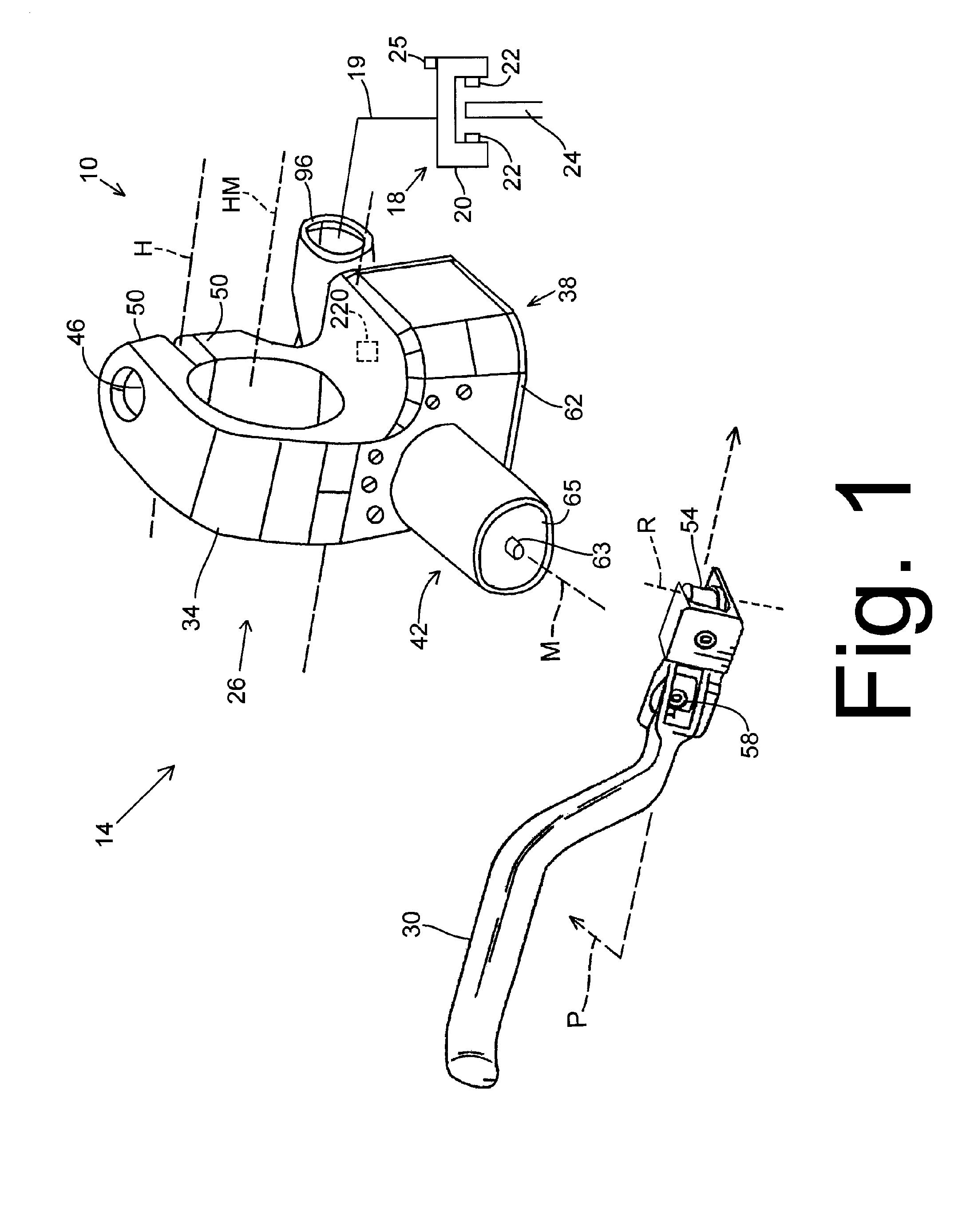
[0009]FIG. 1 is a schematic view of a bicycle brake system 10. Bicycle brake system 10 includes a brake lever assembly 14, a caliper assembly 18, and a brake fluid tube 19 connected between brake lever assembly 14 and caliper assembly 18. Caliper assembly 18 may be a conventional caliper assembly comprising a caliper housing 20 that supports a pair of oppositely facing brake pads 22 that frictionally contact a rotor 24 in response to hydraulic pressure applied to one or more pistons (not shown). A fluid reservoir (not shown) is disposed within caliper housing 20, and a bleeding screw 25 is screwed into caliper housing 20 for bleeding a fluid such as air and / or brake fluid from the fluid reservoir.

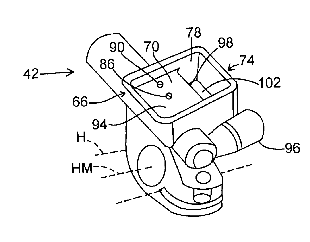
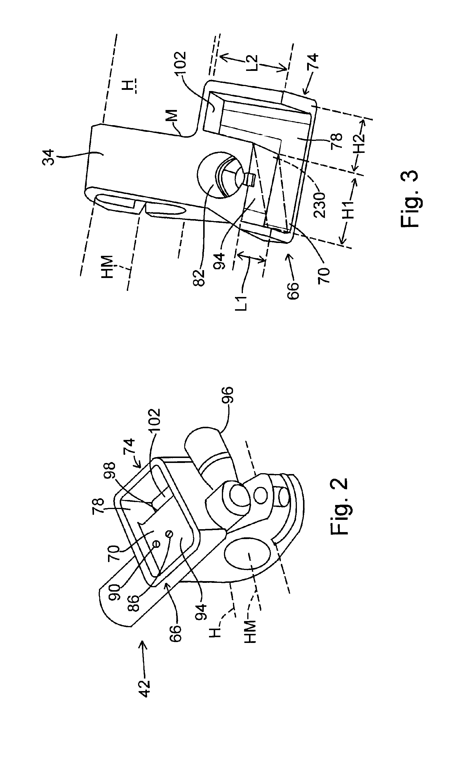
[0010] Brake lever assembly 14 includes a brake lever mounting assembly 26 and a brake lever 30. Brake lever mounting assembly 26 includes a handlebar mount 34 defining a handlebar mounting axis HM, a fluid reservoir 38, and a master cylinder 42. In this embodiment, both reservoir assembly...


PUM


Abstract

A reservoir apparatus for a bicycle brake lever device comprises a master cylinder and a fluid reservoir including first and second reservoirs. The master cylinder has a master cylinder chamber dimensioned for receiving a master cylinder piston therein. The first reservoir has a first reservoir chamber in fluid communication with the master cylinder chamber for supplying a hydraulic fluid to the master cylinder chamber. At least a portion of the first reservoir chamber is disposed below a portion of the master cylinder chamber. The second reservoir has a second reservoir chamber in fluid communication with the first reservoir chamber, wherein the second reservoir chamber includes an air entrainment surface. The air entrainment surface is positioned higher than an upper surface of the first reservoir chamber.

Description

BACKGROUND OF THE INVENTION [0001] The present invention is directed to bicycles and, more particularly, to a hydraulic apparatus for a bicycle brake lever device. [0002] In recent years, some high performance bicycles have been equipped with hydraulic disk brake systems. Hydraulic disk brake systems typically include a caliper housing, first and second brake pads mounted on opposite inner sides of the caliper housing so as to face each other, and one or more pistons that move the first and / or second brake pads towards each other in response to hydraulic pressure created by the actuation of a brake lever assembly mounted to the bicycle handlebar. A rotor that rotates with the bicycle wheel is disposed between the first and second brake pads. The first and second brake pads apply a frictional force to the rotor when they move towards each other in response to the hydraulic pressure created by the actuation of the brake lever assembly, thereby stopping rotation of the rotor and the bi...

Claims


Application Information

Patent Timeline
Patent Type & Authority Applications(United States)
IPC IPC(8): B62L3/00
CPCB60T7/10B60T11/22B60T17/06B62L3/023
Inventor MATSUSHITA, TATSUYAKARIYAMA, OSAMUTAKIZAWA, SHINICHI
Owner SHIMANO INC
Why Eureka
Try Eureka