Effluent sterilizer system

a technology of effluent sterilizer and waste water, which is applied in the direction of water/sludge/sewage treatment, water treatment parameter control, specific water treatment objectives, etc., can solve the problems of system inability to process liquid and solid waste, waste materials that cannot be moved off-site for treatment, and large energy consumption, so as to achieve maximum energy efficiency

Inactive Publication Date: 2007-06-14
ENVIRONMENTAL WASTE INT
View PDF9 Cites 19 Cited by
  • Summary
  • Abstract
  • Description
  • Claims
  • Application Information

AI Technical Summary

Benefits of technology

[0007] The present invention provides a system that utilizes microwave heating, and resistance immersion heating coils, to sterilize biologically contaminated primarily liquid waste (“effluent”), which is essentially institutional sewage and wastewater from laboratory and greenhouse facilities (“contaminated effluent”). The sewage is initially ground in grinder pumps into particles less than a quarter inch in diameter. The process sterilizes the contaminated effluent by heating it to a minimum temperature for a minimum duration at a controlled pressure, and then discharges it to a sanitary drain as “sterilized effluent”. The process maximizes energy efficiency by using a heat exchanger to raise the temperature of the contaminated effluent with heat drawn from the sterilized effluent of the previous batch. The heat exchanger is designed to accommodate the residual particles in the ground sewage waste stream. All solids and particles originally present in the contaminated effluent pass through the system and are discharged as part of the sterilized effluent. The process is controlled and monitored by a programmable logic controller (PLC) and an array of instrumentation.
[0008] The preferred embodiment is accomplished by providing a system for A system for sterilizing contaminated liquid and solid effluent comprising an inlet for receiving the contaminated effluent, pumping means to move the contaminated effluent and sterilized effluent within the system, a pressurized heating vessel for sterilizing the contaminated effluent, comprising heating means for heating the contaminated effluent to a minimum temperature for a minimum duration, the heating means comprising a plurality of magnetron assemblies for directing microwave energy into contaminated effluent in the vessel, a heat exchanger for raising the temperature of the contaminated effluent with heat drawn from the sterilized effluent comprising a first side and a second side, where heat is exchanged as the contaminated effluent moves through the first side and the sterilized effluent simultaneously moves counter-current through the second side and no cross-contamination occurs between the contaminated effluent and the sterilized effluent during the heat exchange, pressurizing means to maintain a pressure in both the pressurized heating vessel and the second side of the heat exchanger that prevents boiling of the contaminated effluent and the sterilized effluent at the minimum temperature, and an outlet for discharging the sterilized effluent.

Problems solved by technology

In many instances, it is impractical or In the case of aqueous liquid waste where flow is more or less constant, it is undesirable and impractical to move these waste materials off-site for treatment.
While there has and continues to be a number of means to heat waste water to the point of sterilization, most involve the use of steam heating and consume large amounts of energy to achieve these ends.
Present systems are unable to process liquid and solid waste without screening out the solid material.
While microwave treatment has been proposed as a method of dealing with such waste, systems have not become widely available which are secure against leakage, environmentally acceptable and economically reasonable.

Method used


Image

  • Effluent sterilizer system
  • Effluent sterilizer system
  • Effluent sterilizer system

Examples


Embodiment Construction

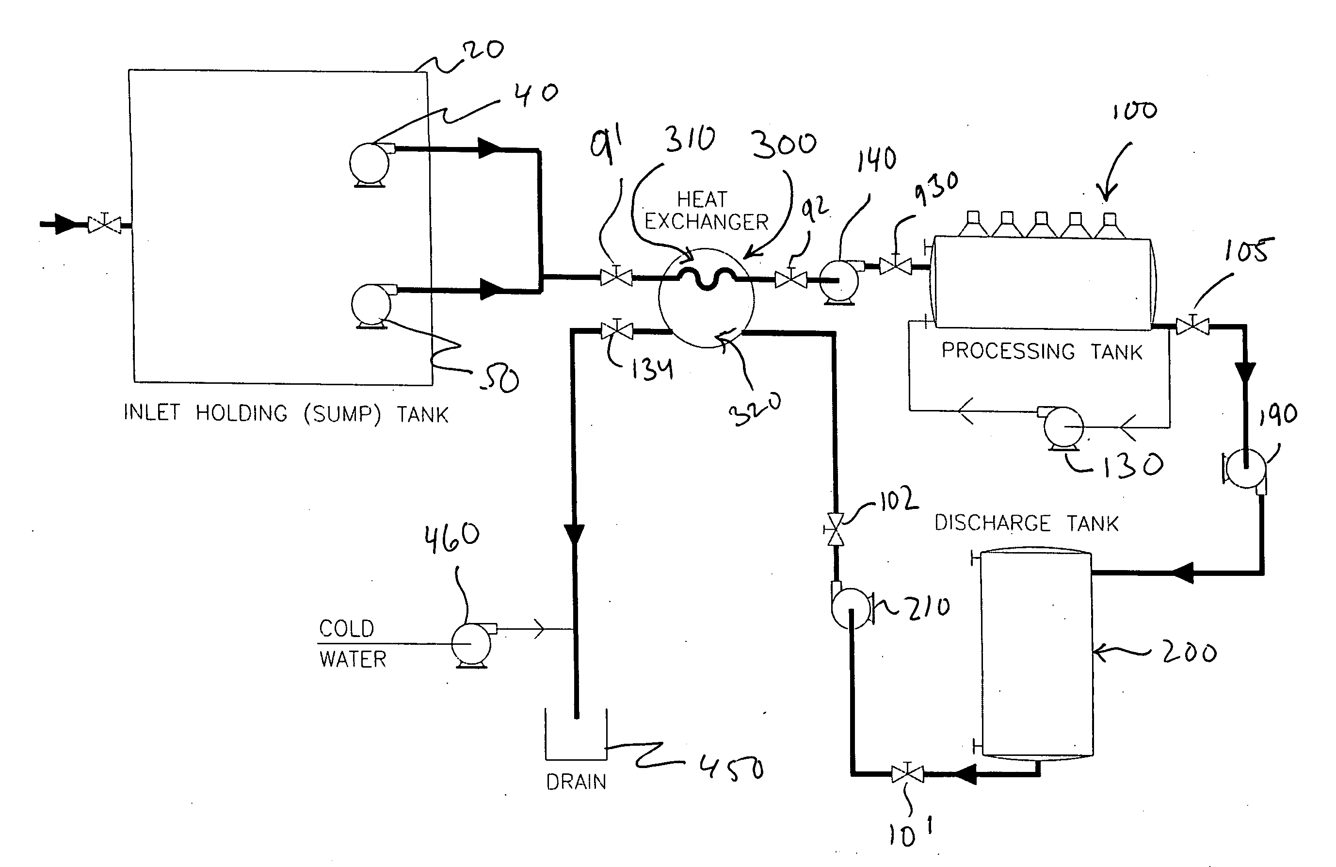
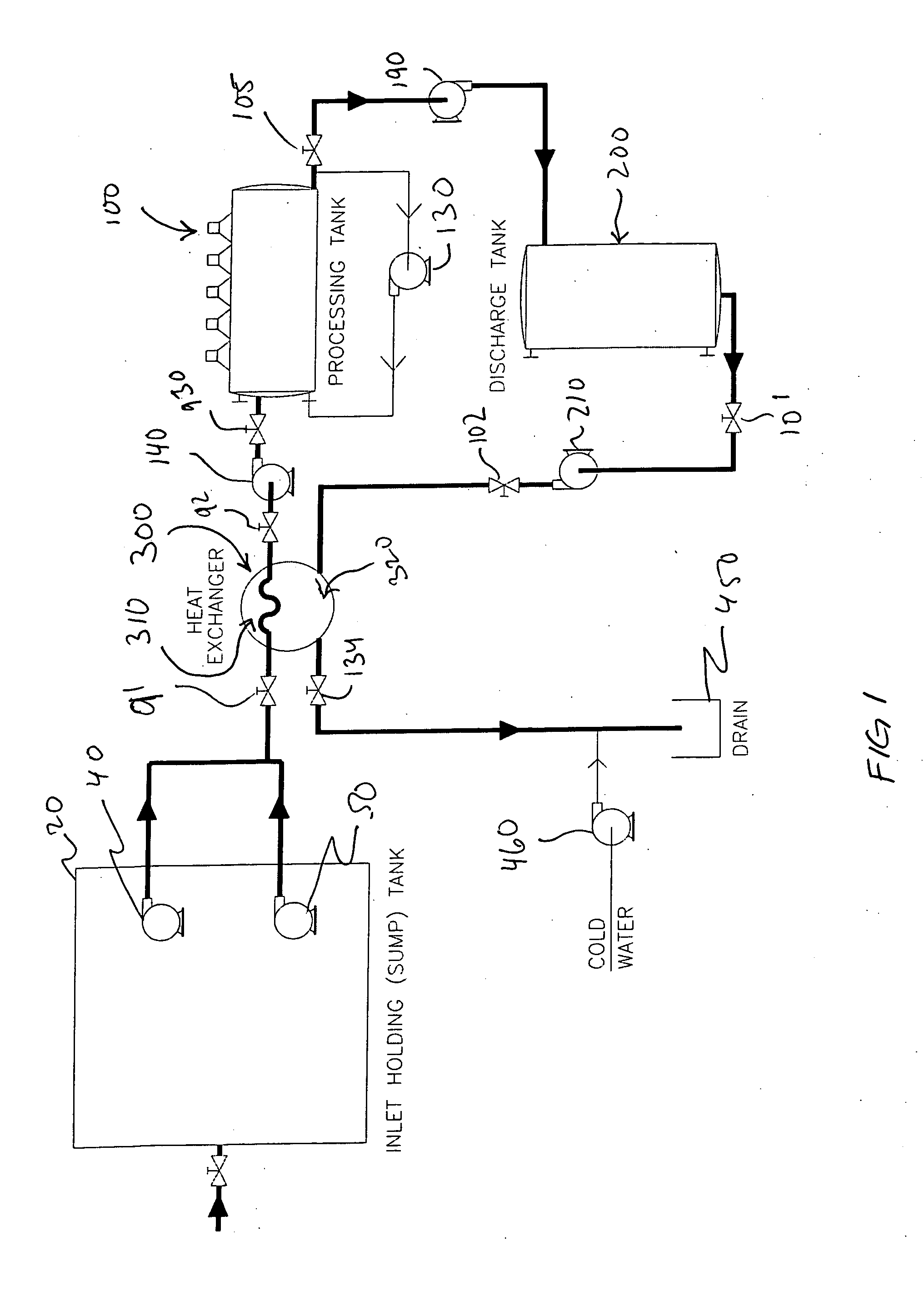
[0015] The present invention provides for the treatment of all waste including solid waste present in ordinary sewage. The sewage is ground by grinder pumps into particles less than a quarter inch in diameter. The ground sewage passes through a heat exchanger designed to accommodate this particle size in a waste stream. One particular use of the invention is in treating laboratory sewage where the effluent must be sterilized.

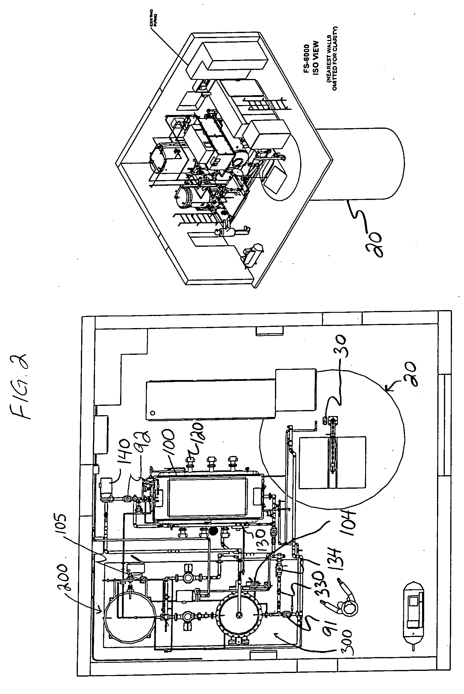
[0016] According to the preferred embodiment shown in FIGS. 1-5, the system contains five main groups of equipment: a processing tank subsystem, an auxiliary skid (which includes a heat exchanger 300, a discharge tank 200, an air compressor, instruments and pumps), the electrical / support group, a sump tank group, and a main air compressor and filters. These groups are all linked through a distributed control system, embodied in a programmable logic controller (PLC), that coordinates the functions of all components, to ensure the safe and efficient treatment of ...


PUM

PropertyMeasurementUnit
temperature sensoraaaaaaaaaa
temperatureaaaaaaaaaa

Abstract

The present invention provides a system that utilizes microwave heating to sterilize contaminated effluent. The system sterilizes the contaminated effluent by heating it to a minimum temperature for a minimum duration under pressure, and then discharging it to a sanitary drain as sterilized effluent. The process maximizes energy efficiency by using a heat exchanger to raise the temperature of the contaminated effluent with heat drawn from the sterilized effluent of the previous batch. All solids and particles originally present in the contaminated effluent pass through the system and are discharged as part of the sterilized effluent.

Description

FIELD OF THE INVENTION [0001] This invention relates to the sterilization of waste. In particular, this invention relates to a system for sterilizing contaminated effluent by heating it using microwave energy to a minimum temperature for minimum duration at a controlled pressure. BACKGROUND OF THE INVENTION [0002] There has long been and continues to be a very significant need for effective means of destroying, sterilizing or otherwise neutralizing waste from a variety of industrial or institutional sources. In many instances, it is impractical or In the case of aqueous liquid waste where flow is more or less constant, it is undesirable and impractical to move these waste materials off-site for treatment. While there has and continues to be a number of means to heat waste water to the point of sterilization, most involve the use of steam heating and consume large amounts of energy to achieve these ends. [0003] For instance, scientific study of new species of pathogens requires sourc...

Claims


Application Information

Patent Timeline
Patent Type & Authority Applications(United States)
IPC IPC(8): C02F1/30
CPCC02F1/02C02F1/302C02F11/185C02F2103/003C02F2201/008C02F2209/005C02F2303/04
Inventor KANTOR, STEVEN L.NORTON, DOUGLASBERNAD, DENES
Owner ENVIRONMENTAL WASTE INT
Why Eureka
Try Eureka