
Method for high flux photocatalytic pollution control

a photocatalytic pollution and high-fluid technology, applied in the direction of physical/chemical process catalysts, arsenic compounds, separation processes, etc., can solve the problems of irregular flow pattern through the mesh, poor catalyst deposition, and uniform catalyst coating, so as to minimize the intrusion of mass transfer

Inactive Publication Date: 2001-11-13
CENT FLORIDA UNIV OF
View PDF11 Cites 26 Cited by
  • Summary
  • Abstract
  • Description
  • Claims
  • Application Information

AI Technical Summary

Benefits of technology

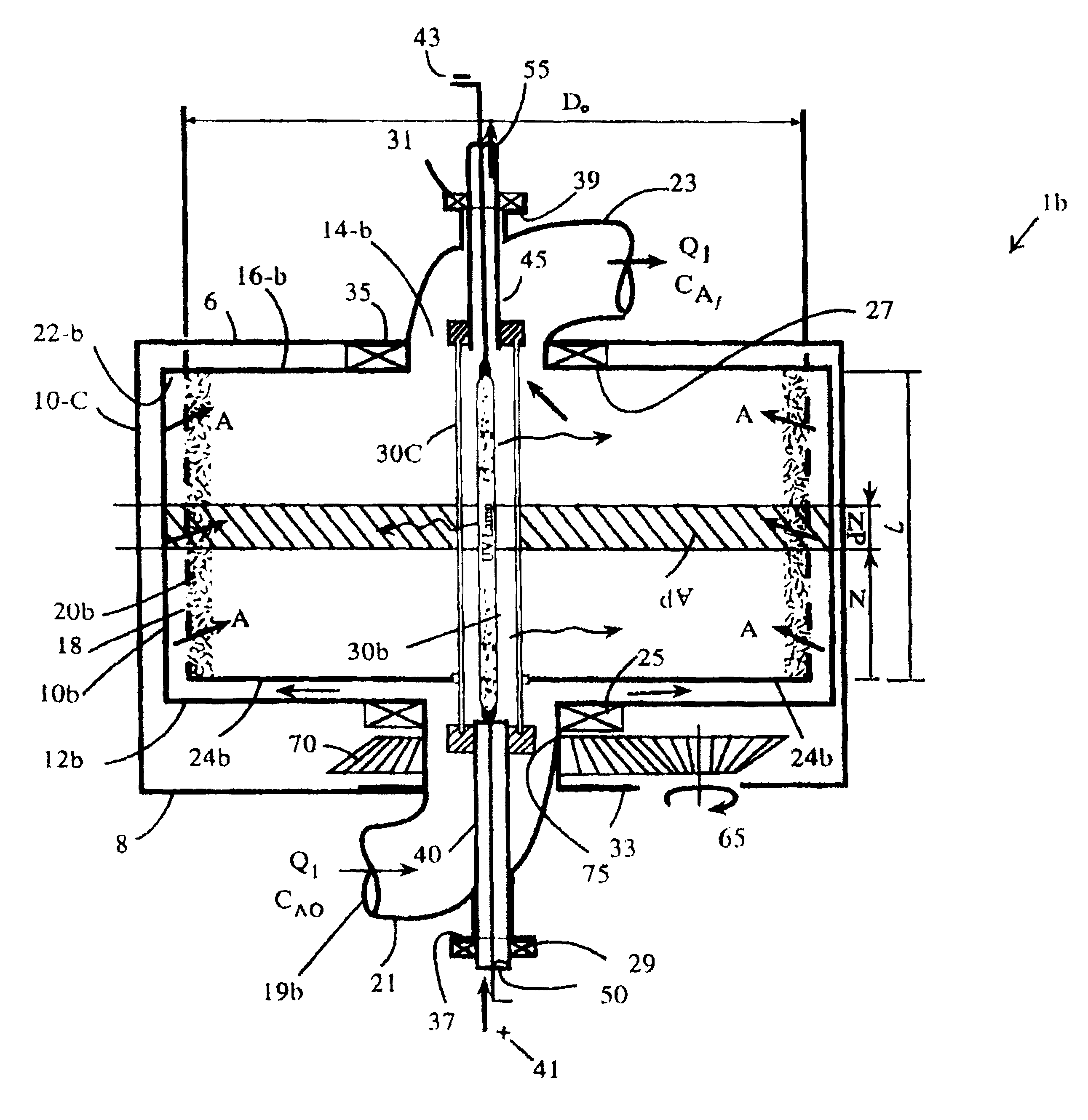
A seventh object of the invention is to allow the contaminant stream to pass through the low-flux media, substantially in lateral direction, in a manner that permits retention of the target species within the low-flux catalytic media in a most efficient manner.
A ninth object of the invention is to provide a flow regime through the single photocell arrangement that minimizes mass transfer intrusions to the low-flux media.
A tenth object of this invention is to provide an optimum configuration that allows most efficient radiant exchange from the light source to the low-flux media and most uniform catalyst surface irradiance.
A twelfth object of the invention is to segment the low-flux photocatalytic media in a single photocell arrangement in a manner that either maximizes the quantum efficiency of the photoprocess or minimizes the pressure drop across the single photocell, ie., the difference between the pressures measured at exit port and inlet port of the single photocell unit.
A seventeenth object of the invention is to arrange and plumb the sub-units of the PPCU in such a manner that either maximizes the overall energy efficiency (apparent quantum efficiency or photoefficiency) of the photocatalytic unit or minimizes the pressure drop across the photocatalytic unit (ie. the difference between the exit port and inlet port pressure).
Therefore, other objects of the invention described here are to provide gas-phase photocatalysis and air purification system with very high process quantum efficiency for treating various organic contaminants including: aliphatics, aromatics, halogenated organics, mercaptants, suffur gases, and others.

Problems solved by technology

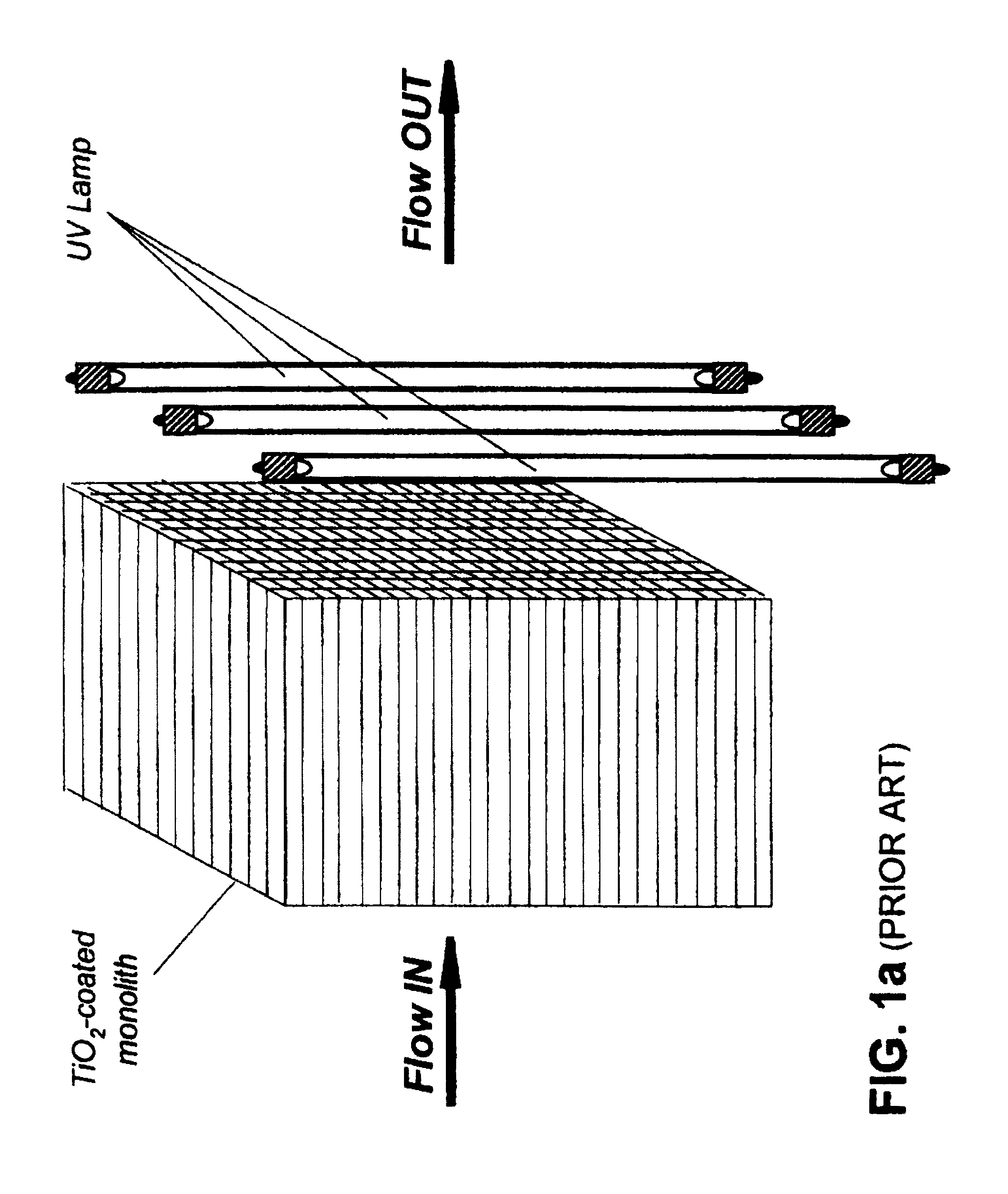
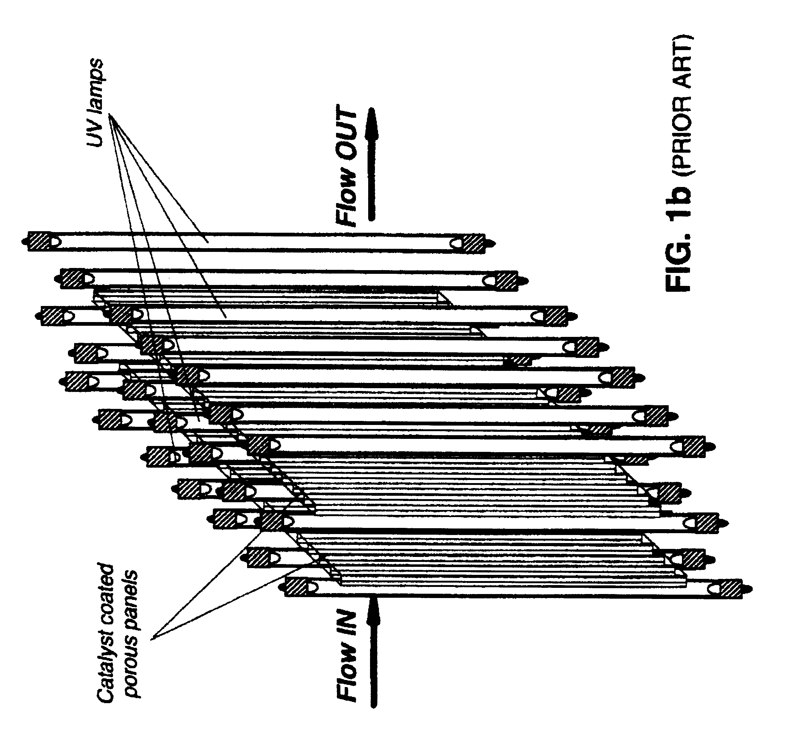
(i) Poor catalyst deposition allows bottom layers of the photocatalyst unexposed to UV light and, hence, not participating in the reactions.
(ii) Non-uniform catalyst coating leads to irregular flow pattern through the mesh.

Method used


Image

  • Method for high flux photocatalytic pollution control
  • Method for high flux photocatalytic pollution control
  • Method for high flux photocatalytic pollution control

Examples


example 1

This EXAMPLE describes the manner in which one preferred embodiment of the invention's low-flux base material / support was prepared. A rectangular piece of unaltered cotton fabric was machine washed in hot water using a small amount of liquid detergent (e.g. Proctor & Gamble's Tides.TM.), followed by two cold rinses. Then, tumble-dried at 55.degree. C., approximately. The entire process above was repeated for the second time. Fabric's post-wash, fully shrunk dimensions were about 95% of the original, as received dimensions. The rectangular piece of fabric was then sewn along the seam and at both ends into cuffs.

example 2

This EXAMPLE describes the manner in which one preferred embodiment of the invention's low-flux catalytic media was prepared. The catalyst in the form of titanium hydroxide, TiO.sub.2 or combination of titanium dioxide and titanium hydroxide was added to the synthetic polymeric, biopolymeric or combination of synthetic polymeric and biopolymeric fibers of the base material / support having a concentration in the range of 1-15 percent by weight of the media (base material and catalyst). The preferred form of the titanium containing catalyst material is in the form of commercial compounds marketed under the trade names such as Kemira UNITI-908.RTM., Degussa P-25.RTM., Hombikat UV100.RTM., Bayer Bayertitan 5585.RTM. and Ishihara ST.RTM. series (e.g. ST-01, ST-11 & ST-31), to name just few.

In one preferred embodiment of the present invention, the catalytic material constitutes titania particles that comprise the crystalline form of anatase or rutile, preferably anatase having BET surface ...

example 3

This EXAMPLE describes the manner in which other preferred embodiments of the low-flux catalytic media were prepared. Different organic, inorganic and metal-organic additives were added to the catalyst slurry of EXAMPLE 2. The solution containing the catalyst and additive was then applied to the base material of EXAMPLE 1. Finally, the supporting base material (fabric) was allowed to dry overnight at room temperature. The preparation method and other details for each additive is given in TABLE I. The rationale for using each additive is disclosed below:

Acridine yellow dye (AY): As an organic dye performs two useful functions: First, being a photocatalyst facilitates various electron transfer reactions (e.g. photogeneration of hydrogen from aqueous solutions of electron donors). Second, as a photosensitizer extends the absorption properties of the base material / support of semiconductor-based photocatalysts. Acridine yellow is one of few organic dyes that perform both functions. For e...


PUM

PropertyMeasurementUnit
wavelengthsaaaaaaaaaa
temperatureaaaaaaaaaa

Abstract

A new method for design and scale-up of photocatalytic and thermocatalytic processes is disclosed. The method is based on optimizing photoprocess energetics by decoupling of the process energy efficiency from the DRE for target contaminants. The technique is applicable to both low- and high-flux photoreactor design and scale-up. The low-flux method is based on the implementation of natural biopolymeric and other low-pressure drop media support for titanium dioxide and other band-gap photocatalysts. The high-flux method is based on the implementation of multifunctional metal oxide aerogels and other media in conjunction with a novel rotating fluidized particle bed reactor.

Description

Examples of treatable streams include, among others, ventilation makeup air, ambient air, air from stripping and off-gassing operations, soil vapor extrartion (SVE), airborne matter (e.g. organic particulate, biogenic and microbial matter) and process vent gas, wastewater treatment off-gas, liquid effluents (e.g. wastewater, industrial and agricultural runoff) containing at least one undesirable or otherwise unwanted compound. Moreover, this application presents a holistic approach to the design of the high performance photo- and thermocatalytic systems that possess:i--Rapid species mass transfer to and from the active sites of the catalyst.ii--Uniform transport of thermal and radiant energy to the active sites of the catalyst.iii--Decoupling of the conversion efficiency from process intrinsic energy efficiency.iv--Minimal pressure drop.As environmental regulations become progressively more stringent, new techniques and approaches are needed for dealing with difficult contaminants. ...

Claims


Application Information

Patent Timeline
Patent Type & Authority Patents(United States)
IPC IPC(8): B01D53/88B01J19/12B01J8/08B01J19/28B01J8/10B01J19/00B01J35/06B01J35/00C02F1/72C02F1/38C02F1/32B01J21/00B01J21/06C02F1/02B01D53/86C02F1/30
CPCB01D53/885B01J8/10B01J19/123B01J19/28B01J35/002B01J35/004B01J35/06C02F1/325C02F1/38C02F1/725B01D2255/802B01J21/06B01J21/063B01J2219/00015B01J2219/00191B01J2219/0877B01J2219/0879B01J2219/0892B01J2219/1946C02F1/02C02F2201/3223C02F2201/328C02F2305/10Y02W10/37
Inventor TABATABAIE-RAISSI, ALIMURADOV, NAZIM Z.MARTIN, ERIC
Owner CENT FLORIDA UNIV OF
Learn More