Pre-aligner

a pre-aligner and lens technology, applied in the field of pre-aligners, can solve the problems of uniform or non-uniform illumination, expensive lens b>20/b>, mechanical limitations of pre-aligner b>10/b>, etc., and achieve the effects of simple and compact packaging, easy removal and replacement, and cheap production

Active Publication Date: 2006-05-09
BOOKS AUTOMATION US LLC
View PDF8 Cites 20 Cited by
  • Summary
  • Abstract
  • Description
  • Claims
  • Application Information

AI Technical Summary

Benefits of technology

[0019]A further aspect of the present invention is to provide a light guide assembly that may be produced inexpensively. In one embodiment, the light guide housing is manufactured from plastic. In another embodiment, the light guide may be easily removed and replaced.
[0020]Still another aspect of the present invention is to provide a pre-aligner whereby little or no recalibration of the LED is required after the light guide assembly has been removed and replaced. In one embodiment, the LED is held in place by a magnet that centers itself w

Problems solved by technology

Specifically, the brightness of the individual LED's 13 will fade at different times. This fading will eventually lead to an uneven or non-uniform illumination.
Such a lens 20 is expensive.
In addition to electrical disadvantages, there are also mechanical limitations to the pre-aligner 10.
The lighting assembly is vulnerable to damage.
Thus, the housing can be easily bent during shipping and handling, or by a collision with a robot arm.
This exacerbation effect must be compensated for by added comp

Method used


Image

  • Pre-aligner
  • Pre-aligner
  • Pre-aligner

Examples


Embodiment Construction

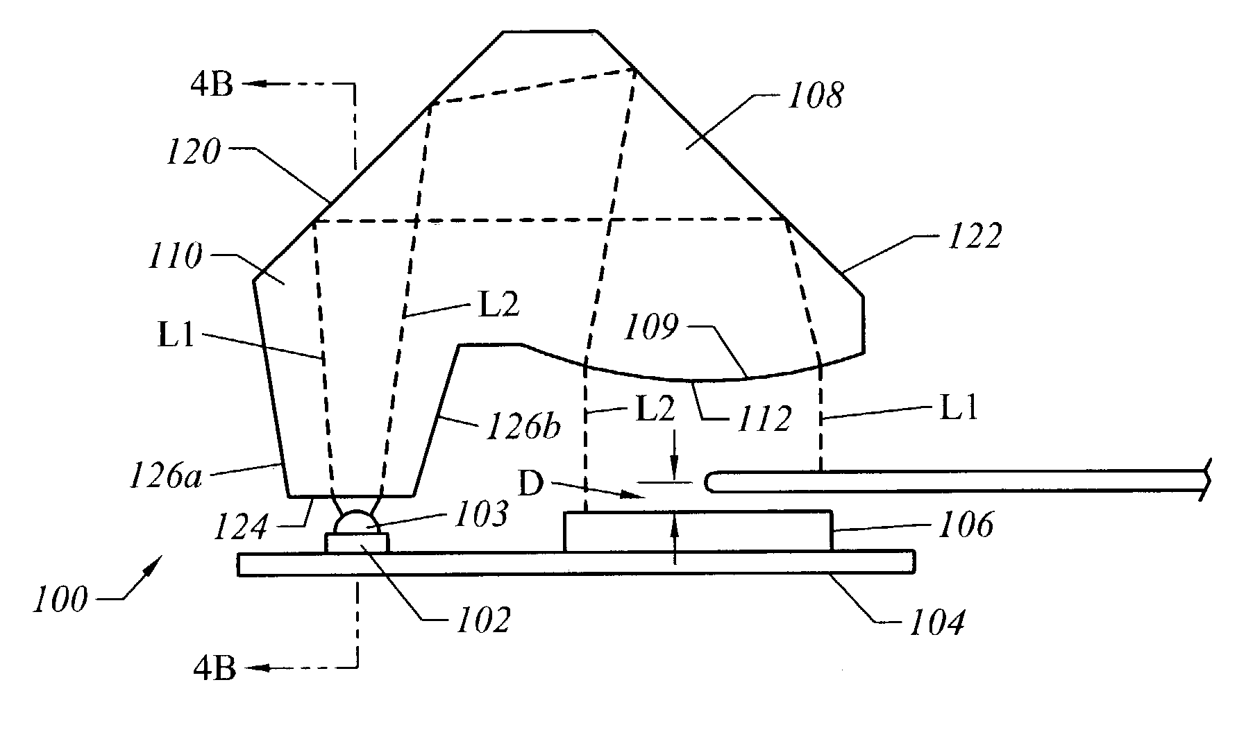
[0032]The present invention, and all the embodiments, will now be described with reference to FIGS. 8–10. In a preferred embodiment, the pre-aligner 100 uses the method of casting a shadow of a wafer edge directly onto a charge coupled device (CCD) linear array.

[0033]As shown in FIGS. 4A–4B, the pre-aligner 100 comprises an LED 102, a PCB 104, a CCD 106, and a light guide 108. An LED 102 is commonly known within to one skilled in the art and does not require further disclosure. The LED 102 is preferably the primary light source for the pre-aligner 100. In a preferred embodiment, a single LED 102 is the only light source for the pre-aligner 100. It is within the scope and spirit of the invention for the pre-aligner 100 to use more than one LED 102. As shown in FIG. 4A, the LED 102 has a light emitting portion 103. The LED 102 is mounted to the PCB 104 such that the light-emitting portion 103 is facing upward—toward the light guide 108.

[0034]As previously discussed above, the LED and ...


PUM


Abstract

The present invention is a pre-aligner capable of determining the center of a wafer by casting light onto a wafer that is positioned above a charge-coupled device (CCD). The pre-aligner performs this operation by directing light emitted from a single LED simultaneously onto the wafer and the CCD. The light emitted from the LED is directed through a light guide in order to direct the light onto the wafer and CCD. A lens collimates the light exiting the light guide such that the light, as it passes the wafer's edge, is substantially perpendicular to the wafer's edge. The light guide may be removably secured to the pre-aligner housing for easy installation removal. The pre-aligner is capable of self-calibrate the LED.

Description

CLAIM OF PRIORITY[0001]This application claims priority to U.S. Provisional Patent Application Ser. No. 60 / 380,993, entitled “Pre-Aligner Light Source,” filed with the U.S. Patent and Trademark Office on May, 16, 2002.FIELD OF THE INVENTION[0002]The present invention generally relates to a pre-aligner for centering a wafer prior to placing the wafer in a processing tool. More specifically, an embodiment of the present invention aligns a wafer by directing the light emitted from a single LED onto a charge coupled device (CCD) light array with a “light guide.”BACKGROUND OF THE INVENTION[0003]In the semiconductor industry, it is common to pre-align a semiconductor wafer as part of readying the wafer for processing. The pre-alignment operation conventionally includes locating and precisely positioning the geometric center of the wafer. Once this operation is complete, the wafer is then placed in a selected orientation related to the orientation of its crystalline structure. This pre-ali...

Claims


Application Information

Patent Timeline
IPC IPC(8): G01B11/00H01L21/68H05K13/00
CPCH01L21/681H05K13/0015
Inventor MAYO, MICHAEL J.
Owner BOOKS AUTOMATION US LLC
Why Eureka
Try Eureka