Method and device for modifying the compression rate to optimize operating conditions of reciprocating piston engines

a technology of reciprocating pistons and compression rates, which is applied in the direction of engines, machines/engines, mechanical equipment, etc., can solve the problems of limited operation hysteresis

Inactive Publication Date: 2004-09-14
INST FR DU PETROLE +1
View PDF8 Cites 21 Cited by
  • Summary
  • Abstract
  • Description
  • Claims
  • Application Information

AI Technical Summary

Benefits of technology

controlling the movement of the point referred to in the first subparagraph of this third phase to cause the compression ratio to approximate the optimum value calculated in the second phase.
For the other feature of the method described in the foregoing paragraph, the compression ratio is measured by measuring a physical magnitude enabling the compression ratio to be calculated, for example: measuring movement of the articulation point. The other physical magnitudes measured according to this method are parts of the physical magnitudes usually taken into account when controlling alternating-piston internal combustion engines. The controlled parameters of the engine for maximizing energy efficiency and minimizing pollution, other than the compression ratio, are part of the controlled parameters normally used in controlling alternating-piston internal combustion engines.
Metering the quantity of air admitted for low loads has several advantages. The temperature at the end of combustion may be lower, thus favoring service life, energy efficiency, and nitrogen oxide emissions control. This is also a relevant parameter for maintaining an engine in the spark ignition operating mode by compressing a premixture of oxidant and fuel. Note that metering the air admitted by adjusting the settings of the inlet valves is relevant for limiting load losses at admission.
The use of some of the enthalpy of the exhaust gases has the advantage that energy wastage through the exhaust system can be reduced, to activate the device modifying the compression ratio in order to improve the energy yield.
According to another feature, a gas cylinder acts on a booster cylinder to supply a hydraulic pressure to modify the compression ratio of the engine. This design offers greater choice in placement of the gas actuator.

Problems solved by technology

The operating hysteresis is limited by the energy supplied by an activator.

Method used


Image

  • Method and device for modifying the compression rate to optimize operating conditions of reciprocating piston engines
  • Method and device for modifying the compression rate to optimize operating conditions of reciprocating piston engines
  • Method and device for modifying the compression rate to optimize operating conditions of reciprocating piston engines

Examples


Embodiment Construction

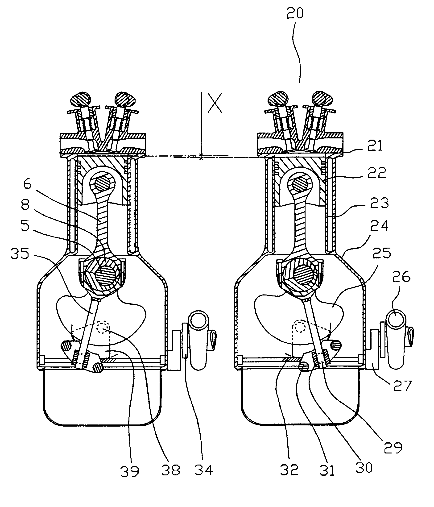
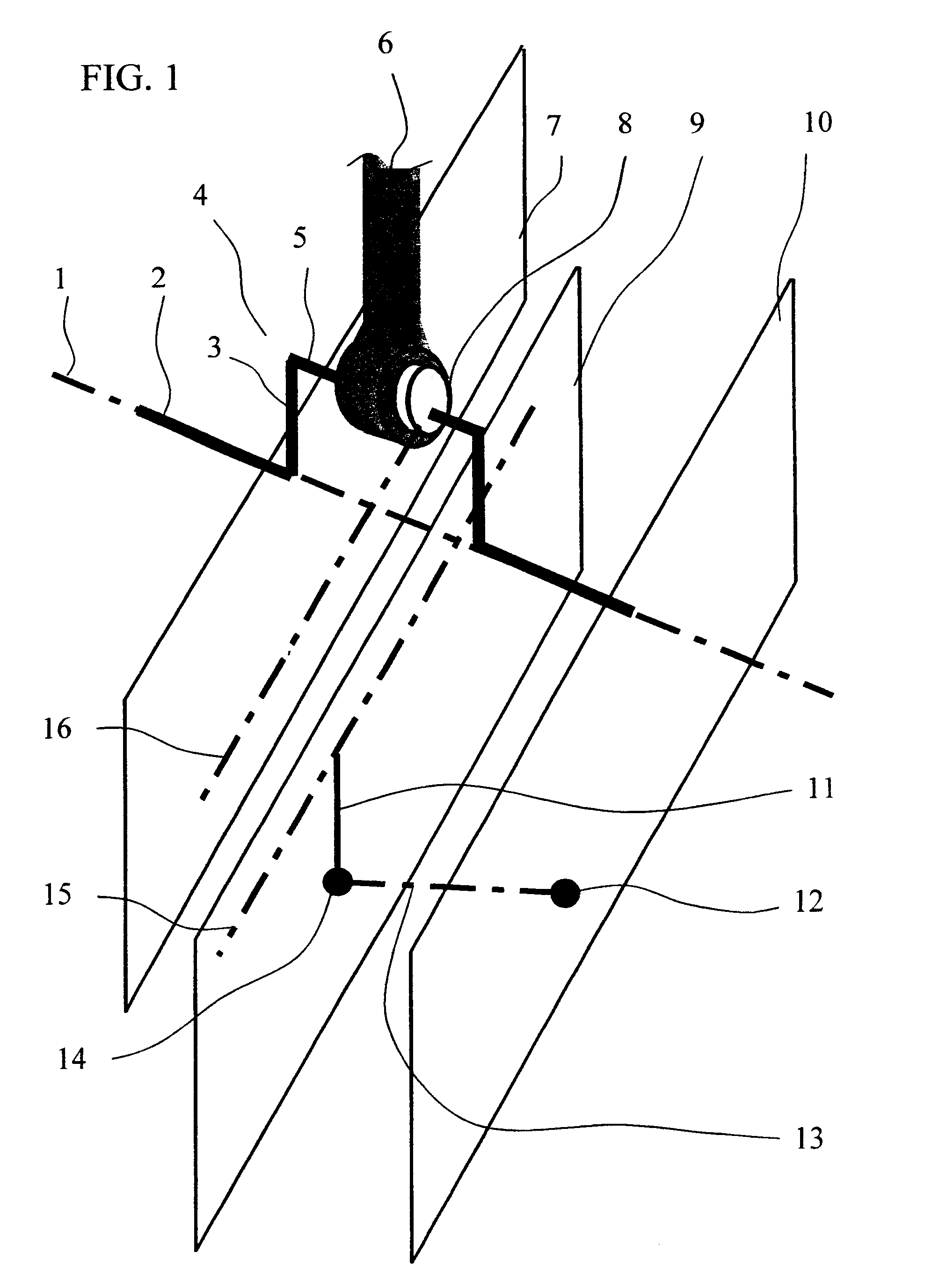
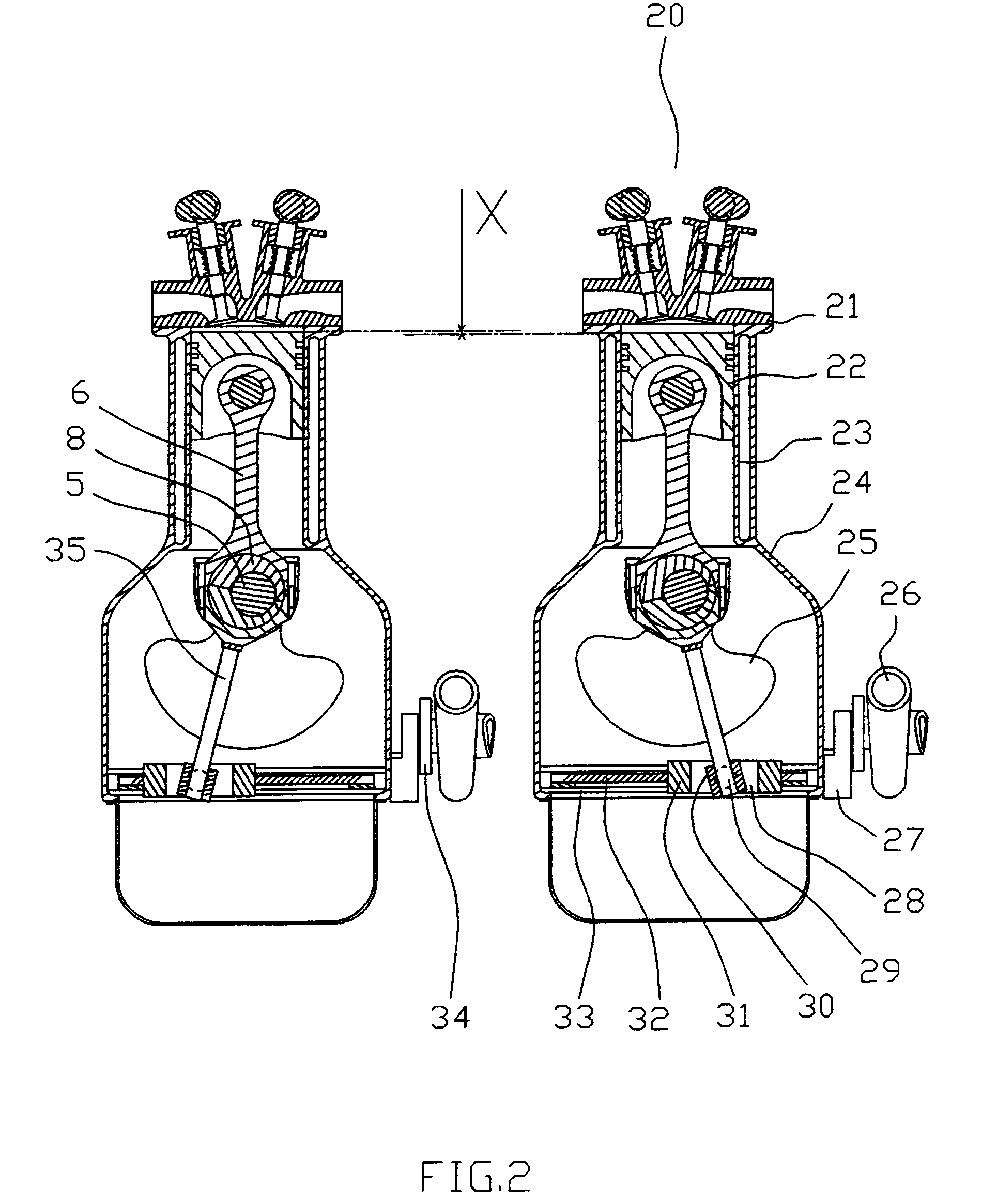
The invention relates to a method and device for continuous optimization of the compression ratio within ranges determined by design, particularly for in-line, V, or opposed engines. The invention has the advantage, as far as the necessary technologies are concerned, of being compatible with the technologies currently used for cylinder heads, cylinder blocks, crankshafts, and their connections with the transmissions. It also has the advantage, as far as its implementation is concerned, of allowing the use of technologies similar to technologies used in alternating-piston engines that are well understood and are of proven reliability. The particular embodiments according to the invention have other advantages listed in this description.

The present invention applies to internal combustion engines with alternating pistons driven by a crankshaft. Each of these engines has one or more combustion chambers and a crankcase. The crankcase is defined in the present description and claims as t...


PUM


Abstract

The invention relates to the modification of the compression ratio using technologies similar to traditional engine parts.Turbines (26) and (81) set up to act in the reverse direction drive a screw (32) and shift the pivot (29) which articulates the rod (35) integral with a cam (8a) located between the foot of connecting rod (6a) and crank pin (5).The invention is intended in particular to increase energy efficiency and reduce engine pollution.

Description

TECHNICAL AREAThe present invention relates to a method and a device that is reactive and consumes very little energy, for continuous optimization of the compression ratio, particularly of alternating-piston engines. This invention is particularly relevant to increasing the energy efficiency of engines that are not used continuously at full load or that use multiple fuels with different octane ratings. This invention is compatible with a very low pollution level and adapts in particular to alternating-piston engines whose cylinders are disposed flat, either in a "V" configuration or in-line. In the present document, the term "compression ratio" designs the geometric compression ratio of an alternating-piston internal combustion engine.PRIOR ARTContinuous optimization of the compression ratio is relevant in reducing fuel consumption and the contribution to the greenhouse effect for applications where the engines are not at full load and for engines that use multiple fuels with differ...

Claims


Application Information

Patent Timeline
Patent Type & Authority Patents(United States)
IPC IPC(8): F02D15/04F02B75/00F02B75/22F02B75/04F02D15/00F02B75/32F02D15/02
CPCF02B75/04F02B75/045F02B75/047F02B75/22F02D15/04F02D15/02
Inventor MARCHISSEAU, MICHEL ALAIN LEON
Owner INST FR DU PETROLE
Why Eureka
Try Eureka