Color display apparatus

a color display and display device technology, applied in the field of color display devices, can solve the problems of low light utilization efficiency, and color display has not yet been realized with a brightness comparable, and achieve the effect of improving light utilization efficiency

Inactive Publication Date: 2007-06-14
CANON KK
View PDF11 Cites 17 Cited by
  • Summary
  • Abstract
  • Description
  • Claims
  • Application Information

AI Technical Summary

Benefits of technology

[0012] An object of the present invention is to provide a color display apparatus of a transflective-type improved in light utilization efficiency compared with a conventional color display apparatus.

Problems solved by technology

As a result, in the present circumstances, the color display has not been realized as yet with a brightness comparable to that of paper.
On the other hand, as a disadvantage of the micro-color filter method, a transmittance is ⅓ of a monochromatic display method, so that a light utilization efficiency is low.
This low light utilization efficiency leads to a high power consumption of a back light or a front light in a transmission-type liquid crystal display apparatus having the back light or a reflection-type liquid crystal display apparatus having the front light.
However, the FSC method requires drive of a display device at very high speed, thus exerting a large load on a drive system.
As a result, an applicable display mode is limited, so that it cannot be said that the FSC method is currently popularized sufficiently.
As described above, the transflective liquid crystal display apparatus has many advantages and has been widely used but, as described more specifically later, is required to give a cell thickness difference of two times between the light transmission area and the light reflection area, thus being accompanied with such a problem that a process load for giving the cell thickness difference within the display device.
Further, the transflective-type display apparatus and has a poor light utilization efficiency compared with the transmission-type display apparatus.

Method used


Image

  • Color display apparatus
  • Color display apparatus
  • Color display apparatus

Examples


example 1

[0167] A liquid crystal display device was prepared in the same manner as in Comparative Example 1 except that each pixel was divided into four subpixels 72, 73, 74 and 75 as shown in FIG. 3(b). At the three subpixels 72, 73 and 75, a lamination electrode consisting of the aluminum electrode and the ITO electrode was disposed to provide a reflection display area. The remaining subpixel 74 was disposed in the subpixel 73 and was not provided with the aluminum electrode so as to provide a transmission display area.

[0168] Of the three subpixels for reflection display, a green color filter was used at one subpixel 72, and the remaining two subpixels 73 and 75 were provided with no color filter because of color display based on retardation. The remaining two subpixels 73 and 75 were disposed at an areal ratio of 1:2 in order to effect area gradation.

[0169] With respect to a retardation of the liquid crystal layer, the cell thickness was adjusted to 5 μm so that an amount of retardation...

example 2

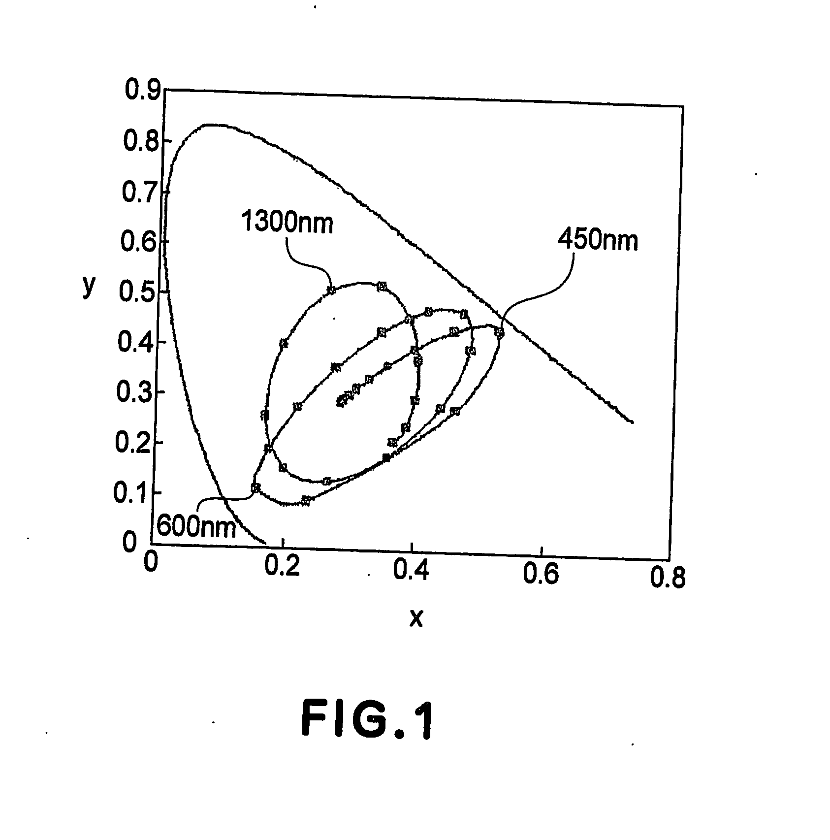
[0174] A liquid crystal display device was prepared in the same manner as in Example 1 except that the subpixel 73 was provided with a magenta color filter (MOdel “CB-571”, mfd. by FUJI FILM Arch Co., Ltd.) having a temperature spectrum characteristic as shown in FIG. 10.

[0175] In the case of utilizing the ECB effect-based coloring phenomenon, a low color purity intrinsic to the retardation color is problematic similarly as in Comparative Example 2. However, in the case of using the green color filter with a color filter of a color complementary to the color of the green color filter in combination, it is possible to cut a tail portion of emission spectrum of red and blue, so that an effect of increasing the color purity is achieved.

[0176] When the above prepared display device was supplied with a voltage at the subpixels provided with the color filter of color complementary to the color of the green color filter, similar as in Comparative Example 2, blue display was effected at 5...

example 3

[0179] A liquid crystal display device was prepared in the same manner as in Example 2 except that the display structure was changed to that shown in FIG. 5 while keeping the same areal ratio between the transmission portion and the reflection portion.

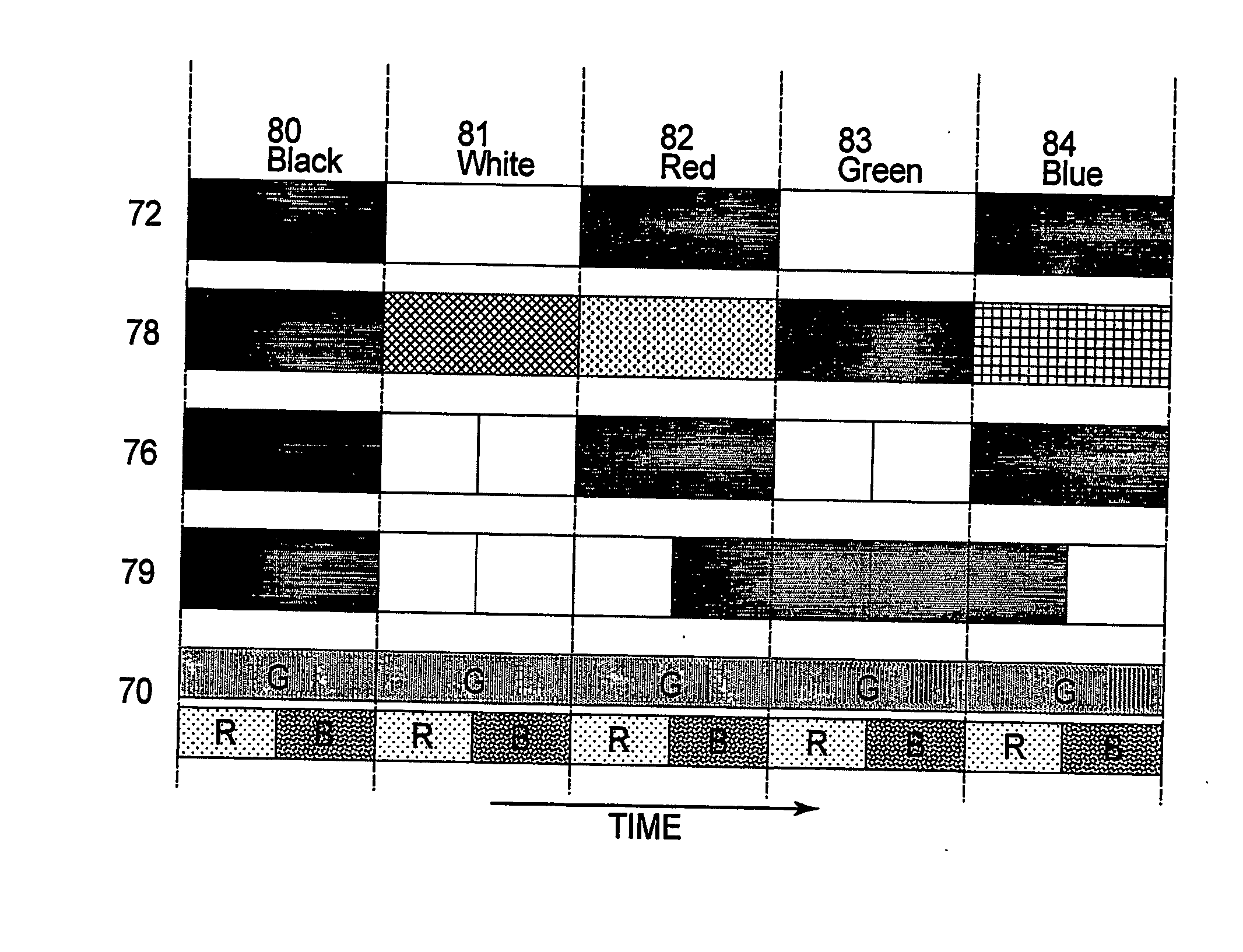
[0180] When the liquid crystal device was driven in the manner shown in FIG. 6, it was confirmed that color display was effected.


PUM

PropertyMeasurementUnit
frequencyaaaaaaaaaa
frequencyaaaaaaaaaa
frequencyaaaaaaaaaa

Abstract

A color display apparatus is consituted by a display panel which has light reflection area and a light transmission area for each pixel , and a light source for causing light to enter said display panel from a back surface of said display panel. The light reflection area includes plurality of subareas including a first subarea in which the incident light is modulated and reflected in a brightness change range within which a brightness of a reflected light is variable and a hue change range within which a hue of a chromatic color assumed by a reflected light is variable and a second subarea provided with a color filter in which incident light is modulated and reflected in a brightness change range within which a brightness of a reflected light is variable. In the light transmission area, the incident light is modulated in a brightness change range within which a brightness of a transmitted light is variable. The light source is periodically switched at least between two lights different in color. The apparatus further comprises means for performing the modulation in the light transmission area in synchronism with the switching in color of said light source.

Description

TECHNICAL FIELD [0001] The present invention relates to a color display apparatus capable of effecting multi-color display and a driving method of the color display apparatus. BACKGROUND OF THE INVENTION [0002] At present, a flat-panel display has widely been popularized as various monitors for a personal computer and the like and as a display device for a cellular phone, and so on. In the future, the flat-panel display is expected to follow popularization more and more, such as development in use for big-screen television. [0003] A most popular flat-panel display is a liquid crystal display. As a color display method for the liquid crystal display, one called a micro-color filter method has been used widely. [0004] Further, in recent years, some display devices, other than the liquid crystal display, excellent in viewability have been reported as an electronic paper display. Most of these devices are intended to realize bright display without using a polarization plate. However, ev...

Claims


Application Information

Patent Timeline
Patent Type & Authority Applications(United States)
IPC IPC(8): G09G3/30G02B5/20G02F1/133G02F1/1335G02F1/13357G02F1/139G09G3/20G09G3/34G09G3/36
CPCG02F1/133555G02F1/133621G02F1/1393G09G3/3607G09G2300/0452G09G2300/0456G09G2300/0491G09G2310/0235
Inventor ASAO, YASUFUMI
Owner CANON KK
Why Eureka
Try Eureka