System for measuring a color property of a liquid

a liquid color and flow cell technology, applied in the field of flow cells for measuring the color properties of liquids, can solve the problems of inability to achieve the goal, and inability to meet the measurement requirements, so as to achieve the effect of reducing the disruption of ligh

Active Publication Date: 2007-06-14
AXALTA COATING SYST IP CO LLC
View PDF30 Cites 10 Cited by
  • Summary
  • Abstract
  • Description
  • Claims
  • Application Information

AI Technical Summary

Benefits of technology

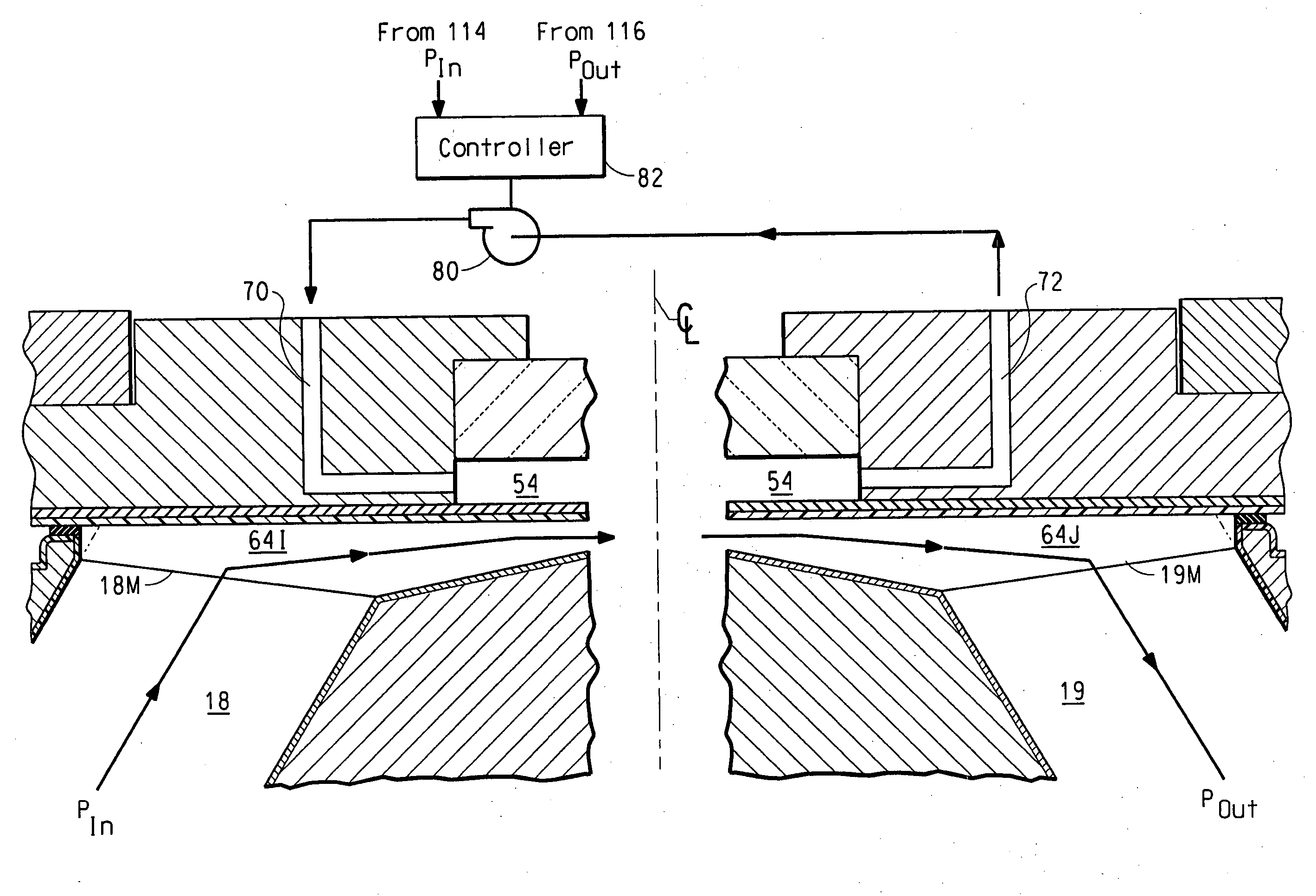
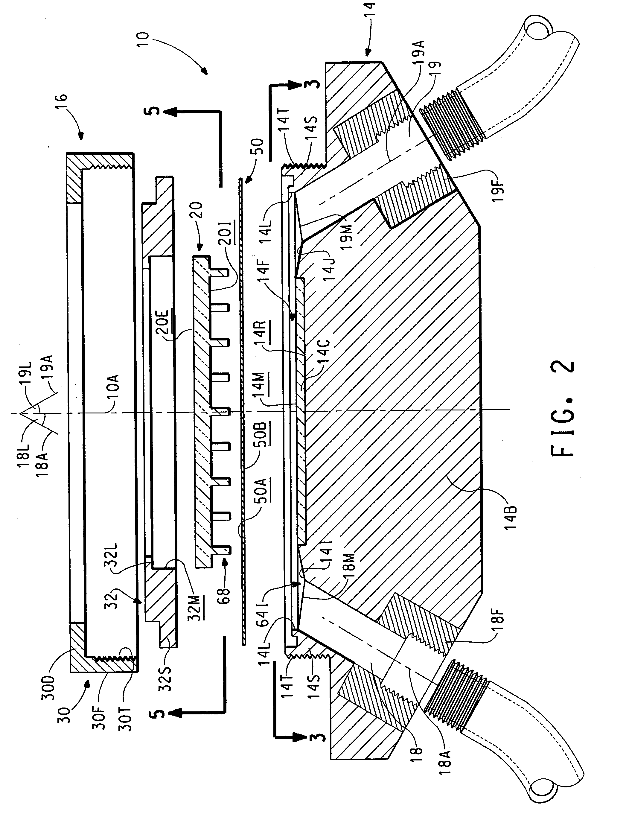
[0039] In a first aspect the present invention is directed toward a method for measuring a color property of a pressurized flowing liquid under test in a way that mitigates the disruption of light. A liquid under test is contacted against a transparent partition that is spaced a predetermined distance from a transparent window. The partition has a predetermined index of refraction and has a thickness dimension that is less than that of the window.

Problems solved by technology

Manual color measurements are very time consuming, primarily due to the long preparation and drying times. Also, the procedure may have to be repeated numerous times before the desired color property is achieved.
This goal has proved elusive.
However, surface non-uniformities of such wet coatings, as well as viscosity variations, settling, and flocculation could still lead to erroneous results and unacceptable measurement variability.
However, coupling such devices as just described to a continuous process has its own encumbering difficulties, including but not limited to, operation of said device in the presence of volatile flammable solvents emitted from the sample surface as well as cleaning.
However, this particular instrument has multiple moving parts which are part of the liquid path, which can cause difficulty in cleaning, and are difficult to maintain.
Another disadvantage is that the instrument requires high volumes of liquid sample to take proper readings.
As a result, in transmission mode no information is provided about scattered light from the fluid being analyzed.
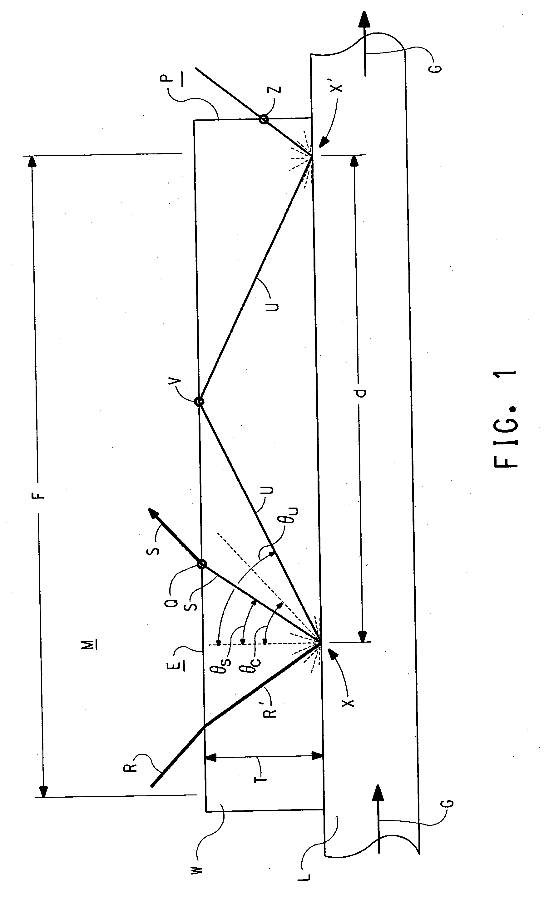
Ultimately, the single most significant issue to overcome in the measurement of the color of a liquid in intimate contact with the window of the flow cell is the disruption of light on its way back to the detector that occurs because of the presence of the window itself.
As a result of such disruption the light ultimately either never reaches the detector or is modified by the surfaces of the window with which it interacts, such that spectral information presented to the detector is no longer truly representative of the sample being measured.
Firstly, the intensity of the scattered light ultimately reaching the detector is diminished.
Secondly, total internal reflection causes the body of the window to exhibit a “glow” effect.
Moreover, since the intensity undergoes different range distortions in different localized wavelength domains, the problem cannot be expeditiously cured by merely scaling the resulting intensity waveform.
Furthermore, if the light is disrupted on its way back to the detector in a way that misrepresents measurement of the true color of the sample, it follows that making adjustments to that color, such as may be required in a manufacturing process, may also be in error.

Method used


Image

  • System for measuring a color property of a liquid
  • System for measuring a color property of a liquid
  • System for measuring a color property of a liquid

Examples


example

[0170] The prevention in light disruption and the corresponding improvements in chroma and in color sensitivity afforded by a flow cell in accordance with the present invention may be understood from the following Example.

[0171] Sample 1 was an orange tint available from E.I. du Pont de Nemours and Co., Wilmington Del. as Tint 853J mixed with a suitable amount of white mixing base to give full spectral information. Sample 2 was the same orange tint doped with 0.32% of a desaturating black colorant available from E.I. du Pont de Nemours and Co., Wilmington Delaware as Tint 806J.

[0172] Reflectance versus wavelength measurements for the two liquid samples Sample 1 and Sample 2 were made using each of three instruments, the Reference Instrument, the Prior Art Comparison Instrument, and the Invention Instrument.

[0173] The Reference Instrument was a rotating disc system generally as described in German Patent DE 25 25 701. Liquid Samples 1 and 2 were separately applied using a slotted ...


PUM

PropertyMeasurementUnit
thicknessaaaaaaaaaa
refractive indexaaaaaaaaaa
interrogating wavelength rangeaaaaaaaaaa

Abstract

A system utilizing the flow cell of the present invention includes a reflectance mode spectrophotometer positioned with respect to the flow cell or a probe. Either the flow cell or the probe has a thin partition mounted in spaced relationship with respect to a transparent window. The partition has a predetermined index of refraction and has a thickness dimension that is less than that of the window. The spacing between the partition and the window is such that evanescent coupling of radiation reflected from the liquid into the material of the window is prevented. The spectrophotometer is directs interrogating radiation toward a liquid flowing through the sample chamber and responds to interrogating radiation reflected from the liquid to produce an electrical signal representative of a color property thereof.

Description

[0001] This application claims the benefit of U.S. Provisional Application; 60 / 742,309 which was filed 05 Dec. 2005, and is incorporated as a part hereof for all purposes. CROSS REFERENCE TO RELATED APPLICATIONS [0002] Subject matter disclosed herein is disclosed and claimed in the following copending applications, all filed contemporaneously herewith and all assigned to the assignee of the present invention: [0003] Liquid Measurement Cell Having A Transparent Partition Therein (FA-1187); [0004] Liquid Measurement Cell Having A Pressurized Air Cavity Therein (FA-1474); [0005] Probe Apparatus For Measuring A Color Property Of A Liquid (FA-1506); and [0006] Method For Measuring A Color Property Of A Liquid (FA-1507).BACKGROUND OF THE INVENTION [0007] 1. Field of the Invention [0008] This invention relates to a flow cell for measuring the color properties of a liquid, such as paint, having liquid flow passages of substantially constant surface area. [0009] 2. Description of the Art [00...

Claims


Application Information

Patent Timeline
Patent Type & Authority Applications(United States)
IPC IPC(8): G01N1/10
CPCG01N21/0303G01N21/4738
Inventor ALSPACH, JEFFJUHASZ, JASONMARTINO, ANTHONYREINHARDT, MATTHEWSCHERMACHER, KENSIMPSON, THOMAS
Owner AXALTA COATING SYST IP CO LLC
Why Eureka
Try Eureka