Apparatus and method for controlling transmission rate in a wireless LAN
Active Publication Date: 2007-06-14
SAMSUNG ELECTRONICS CO LTD +1
5 Cites 30 Cited by
AI-Extracted Technical Summary
Problems solved by technology
A drawback with most of the so-far proposed link adaptation schemes including ARF is that performance decreases drastically in an environment suffering from high radio resource contention.
When many STAs associate with an AP or under severe contention, the probability of collision with frames from another STA or from another AP increases.
However, since the Medium Access Control (MAC) layer of the IEEE 802.11 WLAN assumes a transmission failure solely after a timeout period, it does not distinguish a collision-caused transmission failure from a channel error-caused transmission failure.
This malfunction is more frequent as contention becomes more severe.
When channel errors are generated due to conditions such as path loss, fading or frames c...
Method used
[0030] The present invention provides a WLAN apparatus and method for controlling transmission rate, taking into account collision, in which the cause of a data transmission failure is identified as a channel error or a data collision to thereby reduce a collision-caused rate decrease or a rate increase delay. In the following description, “failure number” refers to th...
Benefits of technology
[0016] A further object of the present invention is to provide an apparatus and method for reduci...
Abstract
An apparatus and method for controlling transmission rate by determining whether a data transmission failure is caused by a channel error or a data collision in order to reduce a collision-caused rate decrease or a collision-caused rate increase delay in a WLAN. A collision-caused data transmission failure and if the number of data transmission failures reaches a predetermined threshold, data is retransmitted by means of an RTS/CTS exchange.
Application Domain
Network traffic/resource managementNetwork topologies +7
Technology Topic
Embedded systemData transmission +3
Image
Examples
- Experimental program(1)
Example
[0029] Preferred embodiments of the present invention will be described herein below with reference to the accompanying drawings. In the following description, well-known functions or constructions are not described in detail since they would obscure the invention in unnecessary detail.
[0030] The present invention provides a WLAN apparatus and method for controlling transmission rate, taking into account collision, in which the cause of a data transmission failure is identified as a channel error or a data collision to thereby reduce a collision-caused rate decrease or a rate increase delay. In the following description, “failure number” refers to the number of data transmission failures and “success number” refers to the number of successful data transmissions.
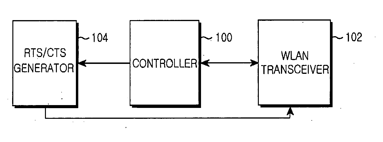
[0031]FIG. 1 is a block diagram of a WLAN apparatus for controlling transmission rate taking into account collision according to the present invention. Referring to FIG. 1, the WLAN apparatus includes a controller 100, a WLAN transceiver 102, and an RTS/CTS generator 104.
[0032] The controller 100 sets a success number to an initial value and increases a failure number when a data transmission failure occurs. When an RTS/CTS exchange triggering condition is fulfilled, the controller 100 triggers an RTS/CTS exchange. If the number of consecutive data transmission failures reaches a threshold, the controller 100 controls data retransmission by decreasing the transmission rate of the WLAN apparatus by one level. The rate control operation of the controller 100 will be described in more detail later with reference to FIG. 4.
[0033] The WLAN transceiver 102 sends/receives data and RTS and CTS frames under the control of the controller 100. The RTS/CTS generator 104 generates the RTS and CTS frames under the control of the controller 100 in compliance with the IEEE 802.11 WLAN standards.
[0034]FIG. 2 is a block diagram of a WLAN apparatus for controlling transmission rate taking into account collision according to another embodiment of the present invention. The WLAN apparatus further includes a collision detector 204 in addition to the configuration of the WLAN apparatus illustrated in FIG. 1, for detecting a collision before RTS/CTS exchange, so that when collisions are not detected, the RTS/CTS exchange mechanism is triggered.
[0035] Referring to FIG. 2, the WLAN apparatus includes a controller 200, a WLAN transceiver 202, the collision detector 204, and an RTS/CTS generator 206. The controller 200 sets a success number to an initial value when a data transmission failure occurs. The controller 200 detects a collision through the collision detector 204. If a collision is detected, the controller 200 controls data to be retransmitted. If collisions are not detected, the controller 200 increases a failure number. When an RTS/CTS exchange triggering condition is fulfilled, the controller 200 triggers an RTS/CTS exchange. If the number of consecutive data transmission failures reaches a threshold, the controller 200 controls data retransmission by decreasing the transmission rate of the WLAN apparatus by one level. The rate control operation of the controller 200 will be described in more detail later with reference to FIG. 5.
[0036] It will be recognized that in another embodiment of the present invention the controller 200 determines that the occurrence time of a data transmission failure is after a collision detection failure. The rate control operation of the controller 200 in this embodiment is will be described later with reference to FIG. 6.
[0037] The WLAN transceiver 202 sends/receives data and RTS and CTS frames under the control of the controller 100. The collision detector 204, when a data transmission has failed, determines whether a data collision has occurred before the RTS/CTS exchange mechanism is triggered under the control of the controller 200. Notably, the collision detector 204 can always detect data collisions. How the collision detector 204 detects collisions and the cases of detectable collisions will be described with reference to FIG. 3.
[0038] The RTS/CTS generator 206 generates the RTS and CTS frames under the control of the controller 100 in compliance with the IEEE 802.11 WLAN standards.
[0039]FIG. 3 illustrates data frame collision types and detectability of collisions in the WLAN. Referring to FIG. 3, the collision detector 204 detects data collisions in a method compliant with the IEEE 802.11 WLAN standard. The WLAN apparatus determines whether a collision has occurred by monitoring a channel a predetermined time, i.e., an SIFS after data transmission.
[0040] Referring to FIG. 3, “STA” is a WLAN apparatus attempting to send data at present and “other” refers to all WLAN apparatuses capable of sending data, expect the STA. Reference numeral 300 denotes collision between data frames of the same duration and reference numerals 302 and 304 denote collisions between data frames of different durations.
[0041] The collision detector 204 can detect only the collision 302 which occurs when a data frame from the STA is shorter in transmission duration than a data frame from another WLAN apparatus by the SIFS or longer. In the other cases, the collision detector 204 cannot find collisions.
[0042] As more data frame sizes are used in the WLAN and as more data rates are used in the WLAN apparatuses, the collision 300 occurs with a very low probability. On the other hand, the collisions 302 and 304 occurs with the same probability. Under the environment with various data frame sizes and data rates, the collisions 302 and 304 may occur simultaneously to different STAs and thus their detection probability is approximately 50%.
[0043] How the above-described WLAN apparatuses control transmission rate, taking into account collision, will be described with references to FIGS. 4, 5 and 6.
[0044]FIG. 4 is a flowchart illustrating a transmission rate control operation in the WLAN apparatus illustrated in FIG. 1 according to the present invention.
[0045] Referring to FIG. 4, the WLAN apparatus determines whether data transmission is successful in step 400. In the case of a data transmission failure, the WLAN apparatus sets the success number to an initial value in step 402, increases the failure number in step 404, and determines whether a RTS/CTS exchange triggering condition is fulfilled in step 406.
[0046] The RTS/CTS exchange triggering condition is when the size of a MAC Protocol Data Unit (MPDU) to be sent is greater than or equal to a predetermined RTS transmission threshold, or the number of data transmission failures is equal to or larger than a predetermined RTS start value. If the data frame size is equal to or larger than the RTS transmission threshold, the failure of the data frame leads to greater consumption of resources. With the RTS start value, the start time of triggering the RTS/CTS exchange mechanism is decided. In the case of a predetermined number of data transmission failures, they may be caused by collision and thus channel resources are reserved by means of the RTS/CTS exchange. The RTS/CTS start value defines the start of the data transmission with the reserved channel resources.
[0047] If the RTS/CTS exchange triggering condition is not fulfilled in step 406, the WLAN apparatus goes to step 412. If the RTS/CTS exchange triggering condition is fulfilled in step 406, the WLAN apparatus sends an RTS frame to a receiving WLAN apparatus in step 408 and monitors reception of a CTS frame in step 410. If the WLAN apparatus fails to receive the CTS frame in step 410, it returns to step 408.
[0048] Upon receipt of the CTS frame in step 410, the WLAN apparatus compares the failure number with a predetermined failure threshold in step 412. If the failure number is less than the failure threshold, the WLAN apparatus retransmits the data in step 416 and returns to step 400.
[0049] If the failure number is greater than or equal to the threshold in step 412, which implies that the number of failed data transmissions equals or exceeds the failure threshold, the WLAN apparatus decreases its transmission rate by one level in step 414, retransmits the data at the decreased rate in step 416, and returns to step 400.
[0050] If the data transmission is successful in step 400, the WLAN apparatus sets the failure number to an initial value in step 418, increases the success number in step 420, and compares the success number with a predetermined success threshold in step 424.
[0051] If the success number is greater than or equal to the success threshold, which implies that the number of successful data transmissions equals or exceeds the success threshold, the WLAN apparatus increases the transmission rate by one level in step 426 and ends the algorithm.
[0052] If the success number is less than the success threshold in step 424, the algorithm is ended.
[0053]FIG. 5 is a flowchart illustrating a transmission rate control operation in the WLAN apparatus illustrated in FIG. 2 according to another embodiment of the present invention. This transmission rate control operation controls transmission rate according to collision detection, the triggering time of the RTS/CTS exchange mechanism, and the number of successive transmission failures, with no regard to collision-caused rate increase delay. It is almost the same as the transmission rate control operation described in FIG. 4, except that a data collision detection procedure is further performed between steps 402 and 404 of FIG. 4.
[0054] Referring to FIG. 5, the WLAN apparatus determines whether data transmission is successful in step 500. In the case of a data transmission failure, the WLAN apparatus sets the success number to an initial value in step 502 and determines whether the RTS/CTS exchange scheme has been performed previously for the failed data frame in step 504.
[0055] The reason for performing step 504 is that if the RTS/CTS exchange scheme was implemented before, this means that collision detection was carried out at least once and another collision detection is useless because other competing WLAN apparatuses are sending short RTS frames after the RTS/CTS exchange.
[0056] If the RTS/CTS exchange was performed before, the WLAN apparatus skips a collision detection step 506, jumping to step 508. If the RTS/CTS exchange has not been performed, the WLAN apparatus performs collision detection in step 506.
[0057] If a collision is detected in step 506, the WLAN apparatus retransmits the data in step 520 and returns to step 500. If collisions are not detected in step 506, the WLAN apparatus increases the failure number in step 508, and determines whether the same RTS/CTS exchange triggering condition, as described in step 406 of FIG. 4, is fulfilled in step 510.
[0058] If the RTS/CTS exchange triggering condition is not fulfilled in step 510, the WLAN apparatus goes to step 516.
[0059] If the RTS/CTS exchange triggering condition is fulfilled in step 510, the WLAN apparatus sends an RTS frame to a receiving WLAN apparatus in step 512 and monitors reception of a CTS frame in step 514. If the WLAN apparatus fails to receive the CTS frame in step 514, it returns to step 512.
[0060] Upon receipt of the CTS frame in step 514, the WLAN apparatus compares the failure number with a predetermined failure threshold in step 516. If the failure number is less than the failure threshold, the WLAN apparatus retransmits the data in step 520 and returns to step 500.
[0061] If the failure number is greater than or equal to the threshold in step 516, which implies that the number of failed data transmissions equals or exceeds the failure threshold, the WLAN apparatus decreases its transmission rate by one level in step 518, retransmits the data at the decreased rate in step 520, and returns to step 500.
[0062] If the data transmission is successful in step 500, the WLAN apparatus sets the failure number to an initial value in step 522, increases the success number in step 524, and compares the success number with a predetermined success threshold in step 526.
[0063] If the success number is greater than or equal to the success threshold in step 526, which implies that the number of successful data transmissions is equal to or exceeds the success threshold, the WLAN apparatus increases the transmission rate by one level in step 528 and ends the algorithm.
[0064] If the success number is less than the success threshold in step 526, the algorithm is ended.
[0065]FIG. 6 is a flowchart illustrating a transmission rate control operation in the WLAN apparatus illustrated in FIG. 2 according to another embodiment of the present invention. This transmission rate control operation controls transmission rate, taking into account collision-caused rate increase delay, collision detection, the triggering time of the RTS/CTS exchange mechanism, and the number of successive transmission failures. It is almost the same as the transmission rate control operation described in FIG. 4, except that a data collision detection procedure is further performed between steps 400 and 402 of FIG. 4.
[0066] Referring to FIG. 6, the WLAN apparatus determines whether data transmission is successful in step 600. In the case of a data transmission failure, the WLAN determines whether the RTS/CTS exchange scheme has been performed previously for the failed data frame for the same reason described before regarding step 504 of FIG. 5, in step 602.
[0067] If the RTS/CTS exchange was performed before, the WLAN apparatus skips a collision detection step 604, jumping to step 606. If the RTS/CTS exchange has not been performed, the WLAN apparatus performs collision detection in step 604.
[0068] If a collision is detected in step 604, the WLAN apparatus retransmits the data in step 620 and returns to step 600.
[0069] If collisions are not detected in step 604, the WLAN apparatus sets the success number to an initial value in step 606, increases the failure number in step 608, and determines whether the same RTS/CTS exchange triggering condition as that in step 406 of FIG. 4 is fulfilled in step 610.
[0070] If the RTS/CTS exchange triggering condition is not fulfilled in step 610, the WLAN apparatus goes to step 616. If the RTS/CTS exchange triggering condition is fulfilled in step 610, the WLAN apparatus sends an RTS frame to a receiving WLAN apparatus in step 612 and monitors reception of a CTS frame in step 614. If the WLAN apparatus fails to receive the CTS frame in step 614, it returns to step 612.
[0071] Upon receipt of the CTS frame in step 614, the WLAN apparatus compares the failure number with a predetermined failure threshold in step 616. If the failure number is less than the failure threshold, the WLAN apparatus retransmits the data in step 620 and returns to step 600.
[0072] If the failure number is greater than or equal to the threshold in step 616, which implies that the number of failed data transmissions equals or exceeds the failure threshold, the WLAN apparatus decreases its transmission rate by one level in step 618, retransmits the data at the decreased rate in step 620, and returns to step 600.
[0073] If the data transmission is successful in step 600, the WLAN apparatus sets the failure number to an initial value in step 622, increases the success number in step 624, and compares the success number with a predetermined success threshold in step 626.
[0074] If the success number is greater than or equal to the success threshold in step 626, which implies that the number of successful data transmissions is equal to or exceeds the success threshold, the WLAN apparatus increases the transmission rate by one level in step 628 and ends the algorithm.
[0075] If the success number is less than the success threshold in step 626, the algorithm is ended.
[0076] A comparison between FIG. 5 and FIG. 6 shows that the step of setting the success number to an initial value is performed at different points of time. In the procedure of FIG. 5, the success number is set to an initial value immediately after the data transmission failure. This implies that a collision-caused rate increase delay is not considered. On the other hand, the success number is set to an initial value when the collision detection fails in the procedure illustrated in FIG. 6. That is, since a data collision is not a channel error-caused transmission failure, the success number is not initialized when a collision is detected.
[0077] In accordance with the present invention as described above, since the cause of a data transmission failure is identified as a channel error or a data collision, a collision-caused rate decrease or a collision-caused rate increase delay is reduced.
[0078] While the invention has been shown and described with reference to certain preferred embodiments thereof, it will be understood by those skilled in the art that various changes in form and details may be made therein without departing from the spirit and scope of the invention as defined by the appended claims.
PUM


Description & Claims & Application Information
We can also present the details of the Description, Claims and Application information to help users get a comprehensive understanding of the technical details of the patent, such as background art, summary of invention, brief description of drawings, description of embodiments, and other original content. On the other hand, users can also determine the specific scope of protection of the technology through the list of claims; as well as understand the changes in the life cycle of the technology with the presentation of the patent timeline. Login to view more.
Similar technology patents
Amorphous silicon thin film transistor
Owner:上海易密值半导体技术有限公司
Novel Cyclic Peptides and Methods Using Same
Owner:DREXEL UNIV
Novel process for the preparation of 3-amino-pentan-1,5-diol
Owner:ROCHE CAROLINA
Compositions and methods of treatment with stem cells
Owner:MARCH KEITH LEONARD +1
Classification and recommendation of technical efficacy words
- reduce rate
Chemical cleaning backwash for normally immersed membranes
Owner:COTE PIERRE LUCIEN +2