Hydrodynamic bearing device, motor, recording disc driving apparatus and assembly jig

a technology of hydraulic bearings and bearings, which is applied in the direction of bearings, shafts and bearings, rotary bearings, etc., can solve the problems of difficult to tell whether the lubricant has leaked or not, motor lock, and difficulty in keeping the nrro (non-repetitive run out) to 100 nm or less with conventional ball bearings, so as to prevent the lubricant that fills the bearings from leaking out and prevent air

Active Publication Date: 2007-06-14
PHC HLDG CORP
View PDF0 Cites 51 Cited by
  • Summary
  • Abstract
  • Description
  • Claims
  • Application Information

AI Technical Summary

Benefits of technology

[0056] With the present invention, it is possible to prevent the lubricant that fills the bearings from leaking out, and prevent air bubbles from infiltrating the bearings, even if the open end of a bearing should be blocked off by a fi

Problems solved by technology

However, since this is limited to the amount of installation space that is available, it is necessary at the same time to increase the recording capacity of each individual HDD.
Meanwhile, there has been a sharp increase in the planar recording density of HDDs, and particularly the track density, and it has been difficult to keep NRRO (Non-Repetitive Run Out) to 100 nm or less with conventional ball bearings, and from the standpoint of noise and impact resistance as well, b

Method used


Image

  • Hydrodynamic bearing device, motor, recording disc driving apparatus and assembly jig
  • Hydrodynamic bearing device, motor, recording disc driving apparatus and assembly jig
  • Hydrodynamic bearing device, motor, recording disc driving apparatus and assembly jig

Examples


first embodiment

(1) Summary

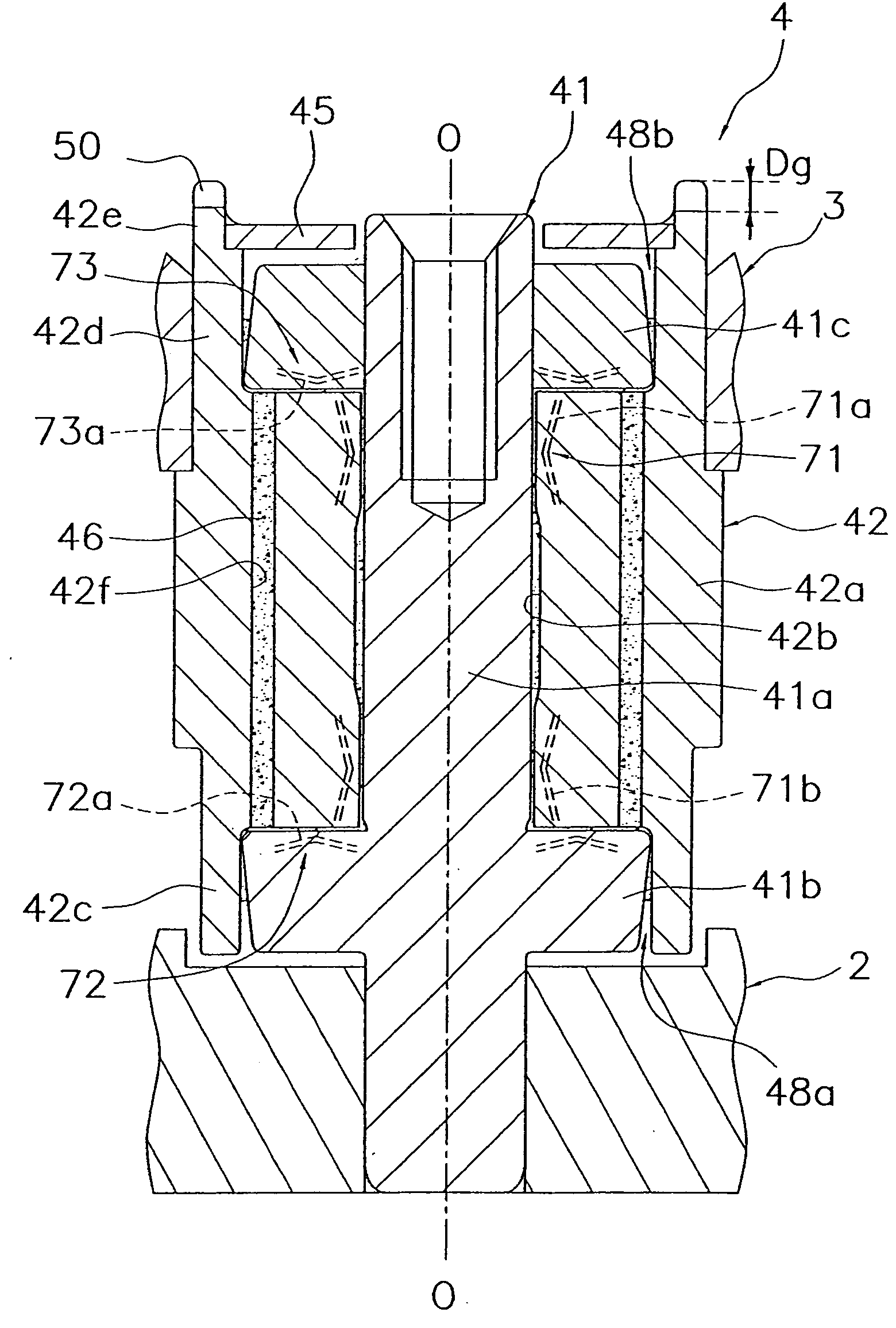
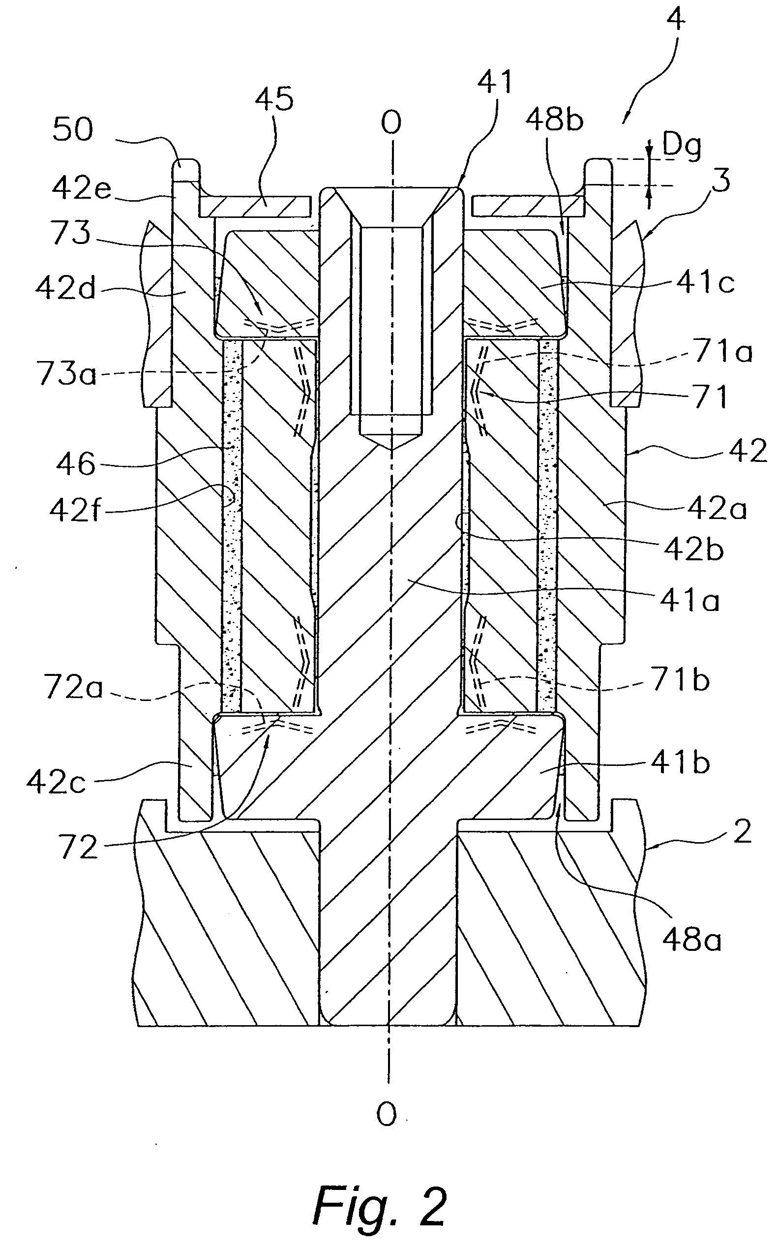
[0058] A first embodiment of the present invention will now be described through reference to FIGS. 1 to 3. The spindle motor that constitutes this first embodiment is equipped with a hydrodynamic bearing device of the type in which the shaft is fixed and the device is open at both ends. This hydrodynamic bearing device is characterized in that a communication mechanism for communicating between the radial inner space and outer space of the sleeve is provided at one end of the sleeve. This will be described in more detail in “(4) Communication Mechanism.”

(2) Spindle Motor Configuration

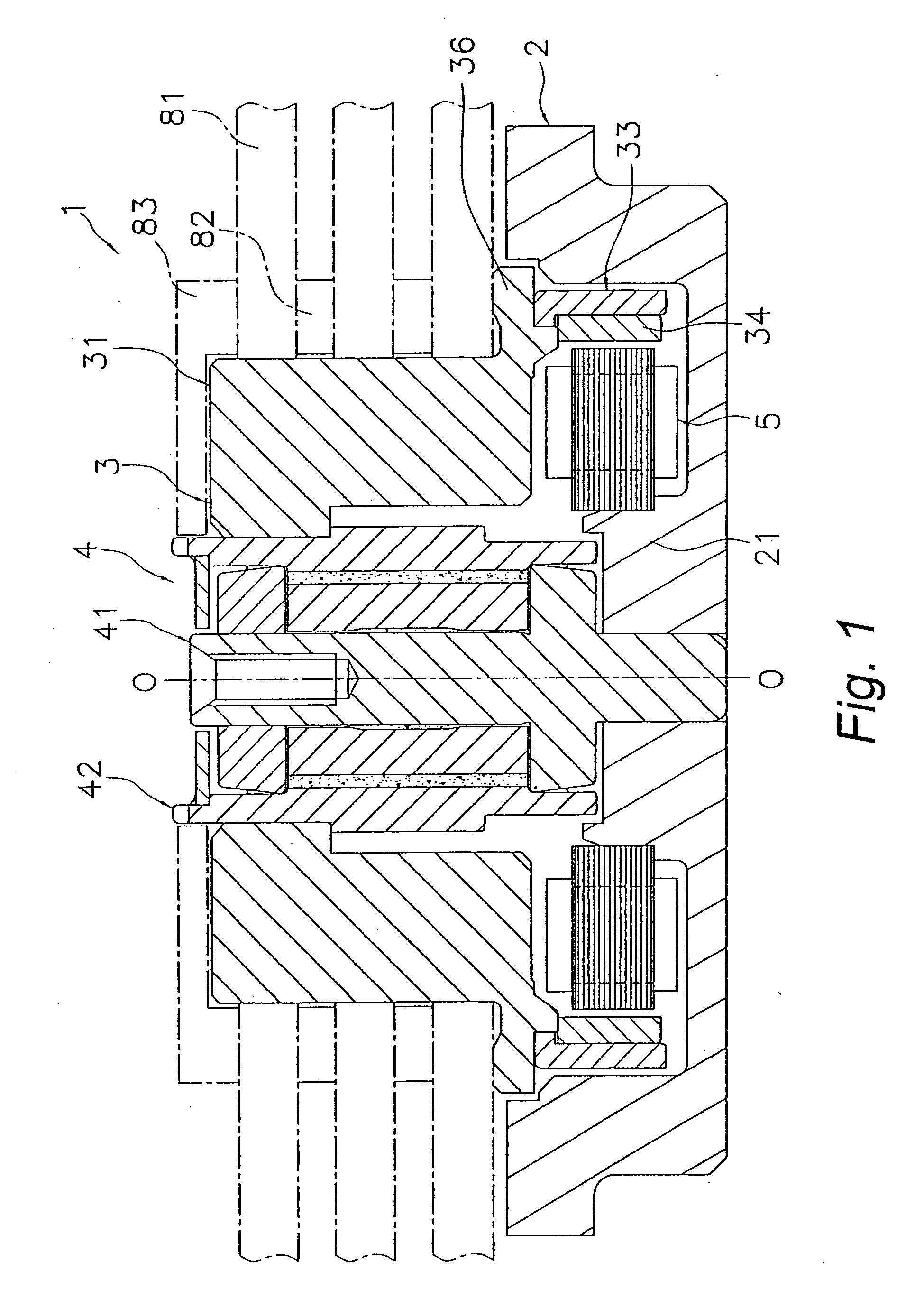
[0059]FIG. 1 is a simplified vertical cross section of a spindle motor 1 in the first embodiment of the present invention. O-O in FIG. 1 is the rotational axis of the spindle. motor 1. For the sake of convenience, the up and down directions in the drawings will be referred to as the “axial upper side,”“axial lower side,” and so forth in the description of this embodiment, but the actual ...

second embodiment

[0158] The hydrodynamic bearing device in a second embodiment of the present invention will now be described through reference to FIG. 16. Those portions that are the same as in the first embodiment above will not be described again. FIG. 16 is a simplified vertical cross section of a hydrodynamic bearing device 4′ as a second embodiment of the present invention. The hydrodynamic bearing device 4′ has a rotor (not shown) rotatably supported by a base plate (not shown), and has a sleeve 142 and a shaft 141.

[0159] The sleeve 142 is a member on the rotating side of the hydrodynamic bearing device 4′, and is a cylindrical member disposed so as to be capable of relative rotation with respect to the shaft 141 discussed below. A radial bearing 171 is constituted between the inner peripheral cylindrical face of the sleeve 142 and the outer peripheral face of the shaft 141. Below the sleeve 142, a thrust bearing 172 is constituted across from a thrust flange 141c fixed or integrally machine...

third embodiment

[0166] The hydrodynamic bearing device in a third embodiment of the present invention will now be described through reference to FIG. 17. Those portions that are the same as in the first embodiment above will not be described again. FIG. 17 is a simplified vertical cross section of a hydrodynamic bearing device 4″ as a third embodiment of the present invention. The hydrodynamic bearing device 4″ has a rotor (not shown) rotatably supported by a base plate (not shown), and has a sleeve 242 and a shaft 241.

[0167] The sleeve 242 is a member on the rotating side of the hydrodynamic bearing device 4″, and is a cylindrical member disposed so as to be capable of relative rotation with respect to the shaft 241 discussed below. A radial bearing 271 is constituted between the inner peripheral cylindrical face of the sleeve 242 and the outer peripheral face of the shaft 241. Below the sleeve 242, a thrust bearing 272 is constituted across from a thrust flange 241c fixed or integrally machined ...


PUM


Abstract

Object: To prevent the lubricant that fills a bearing from leaking out, and prevent air bubbles from infiltrating the bearing, even if the open end of a bearing should be blocked off by a finger or the like in the course of assembling a hydrodynamic bearing device, etc.
Means for Solution: A hydrodynamic bearing device 4 comprises a shaft 41, a second thrust flange 41c, a sleeve 42, a radial bearing 71, and a thrust bearing 73. The second thrust flange 41c is fixed near one end of the shaft 41. A third cylindrical protrusion 42e that protrudes farther in the axial direction than the second thrust flange is fixed to or integrally machined at one end of the sleeve 42. A notch 50 that communicates between a radial inner space and a radial outer space separated by the third cylindrical protrusion 42e is provided to the third cylindrical protrusion 42e.

Description

TECHNICAL FIELD [0001] The present invention relates to a hydrodynamic bearing device, a motor and a recording disk driving apparatus equipped with this hydrodynamic bearing device, and an assembly jig used in the assembly of a hydrodynamic bearing device or an apparatus equipped with this hydrodynamic bearing device. BACKGROUND ART [0002] The popularity of video distribution over the Internet has brought with it a need to increase the recording capacity of the servers that serve as information sources for such distribution. To this end, an increase in data distribution speed and recording capacity has been accomplished in server applications by employing a RAID structure. The number of hard disk drives (hereinafter referred to as HDDs) has to be increased to use a RAID structure, so the general practice has been to install a plurality of HDDs in a tower housing. However, since this is limited to the amount of installation space that is available, it is necessary at the same time to...

Claims


Application Information

Patent Timeline
IPC IPC(8): F16C32/06
CPCF16C17/10F16C33/107F16C33/74F16C2370/12F16C17/107F16C43/02
Inventor NISHIMOTO, YOUICHIKAINOH, NAOSHIMATSUMOTO, TSUYOSHI
Owner PHC HLDG CORP
Why Eureka
Try Eureka