Prismatic sealed rechargeable battery, battery module, and battery pack

Active Publication Date: 2007-06-14
PANASONIC CORP +1
View PDF6 Cites 16 Cited by
  • Summary
  • Abstract
  • Description
  • Claims
  • Application Information

AI Technical Summary

Benefits of technology

[0012] In light of the above-mentioned problems of the conventional techniques, an object of the present invention is to provide a prismatic sealed rechargeable battery which

Problems solved by technology

Moreover, since the battery case is made of metal,

Method used


Image

  • Prismatic sealed rechargeable battery, battery module, and battery pack
  • Prismatic sealed rechargeable battery, battery module, and battery pack
  • Prismatic sealed rechargeable battery, battery module, and battery pack

Examples


embodiment 1

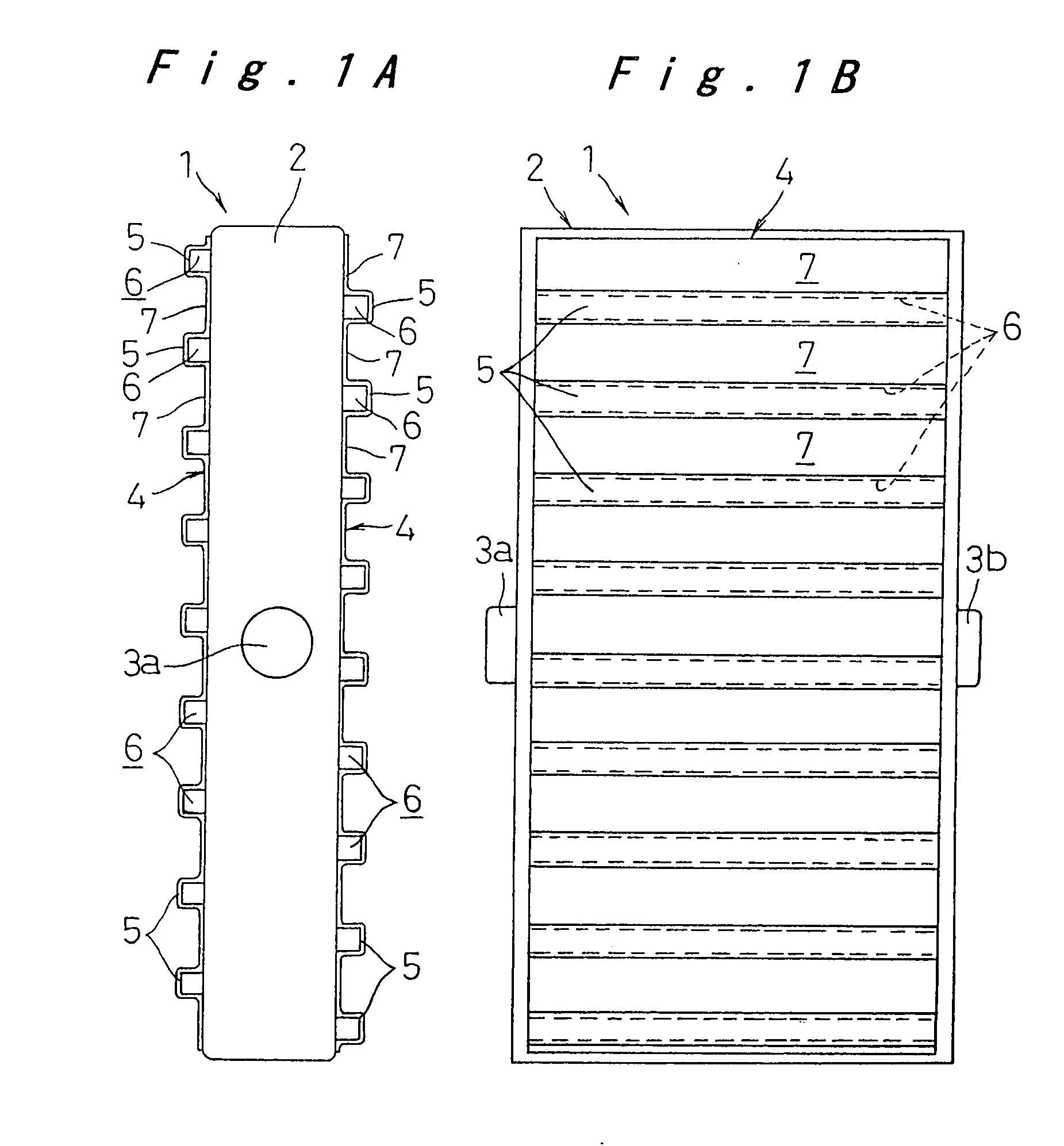
[0020] A prismatic sealed rechargeable battery and a battery module according to a first embodiment of the invention will be described below, with reference to FIGS. 1A, 1B, and 2.

[0021] Referring to FIGS. 1A and 1B, a prismatic sealed rechargeable battery 1 includes a substantially prismatic battery case 2 formed of metal that accommodates an electrode plate assembly and an electrolyte solution. The electrode plate assembly is formed by stacking a plurality of positive electrode plates and a plurality of negative electrode plates with a separator interposed therebetween. The battery case 2 is formed by a steel plate having a thickness of about 0.3 mm to 1.0 mm that is nickel-plated in order to ensure electrolyte-resisting properties. On a pair of shorter side faces of the battery case 2 along a direction perpendicular to the longitudinal direction of the case 2, i.e., left and right side faces of the battery case 2 in FIG. 1B, a positive connection terminal 3a connected to the pos...

embodiment 2

[0033] A battery module using a prismatic sealed rechargeable battery according to a second embodiment of the invention will be described with reference to FIGS. 3A-3C.

[0034] In the present embodiment, a prismatic sealed rechargeable battery 10 constituting a battery module 11 has basically the same structure as that described in the first embodiment. Thus, the same components as those described in the first embodiment are labeled with the same reference numerals, and differences between the first and second embodiments will be mainly described.

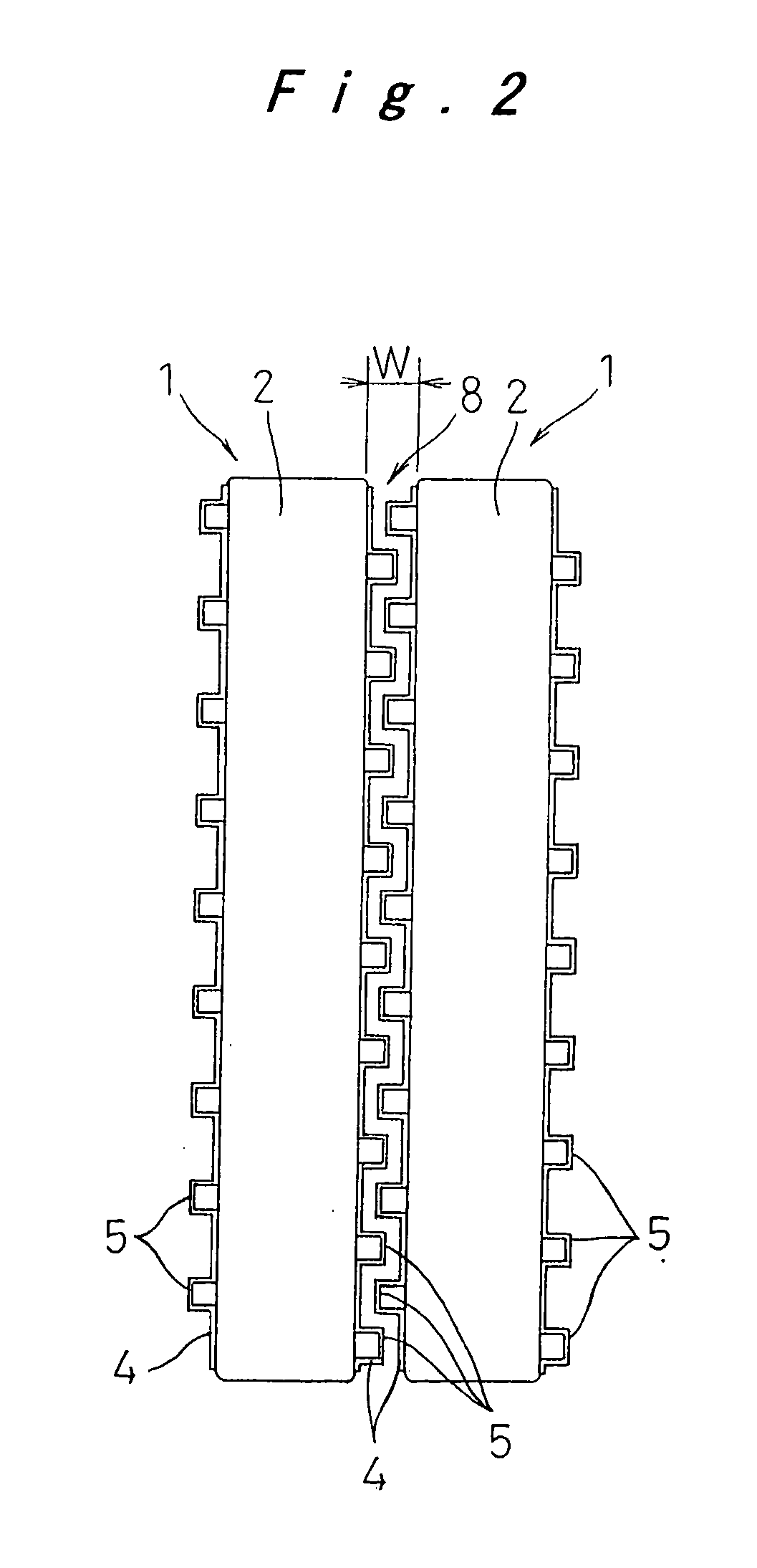
[0035] As shown in FIG. 3B, the battery module 11 includes a plurality of (six in the shown example) prismatic sealed rechargeable batteries 10 that are arranged in a direction parallel to the longer side faces in such a manner that the shorter side face of the battery 10 on which the positive or negative connection terminal 3a or 3b is provided is opposed to the shorter side face of the adjacent battery 10 on which the negative or positive...

embodiment 3

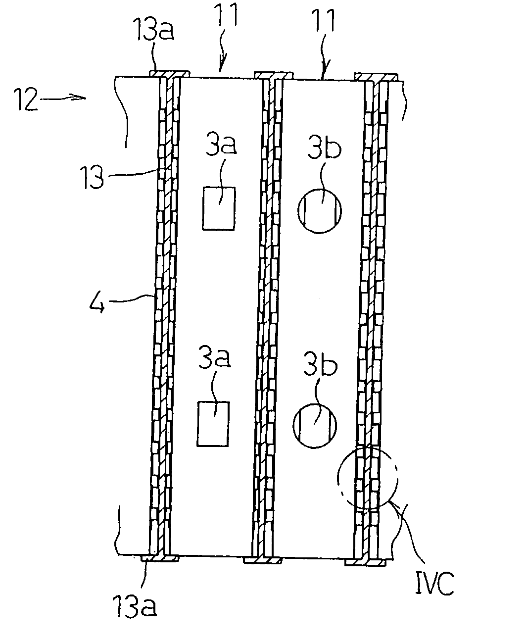
[0041] Next, a battery pack according to a third embodiment of the invention will be described with reference to FIGS. 4A-4C.

[0042] As shown in FIGS. 4A and 4B, a battery pack 12 includes a plurality of battery modules 11 arranged in parallel. The battery modules 11 are electrically connected in series one by one and a plate-like insulator 13 is interposed between the thin plates 4 of the adjacent battery modules 11.

[0043] In the shown example, the protruding portions 5 of the thin plate 4 are formed to have a rectangular cross section in such a manner that the protruding portions 5 on the battery module 11 are opposed to those on the adjacent battery module 11. The insulator 13 is interposed between the opposed protruding portions 5. The insulator 13 has engagement flanges 13a having T-shaped cross section at upper and lower ends thereof. By engagement of the engagement flanges 13a with the upper end face and lower end face of the battery module 11, the insulator 13 is held.

[004...


PUM


Abstract

A prismatic sealed rechargeable battery includes a substantially prismatic battery case that accommodates an electrode plate assembly and an electrolyte solution. The battery case is formed of metal. On a side face of the battery case, a thin plate is provided which has a plurality of protruding portions formed in parallel at appropriate intervals. The protruding portion and the side face form spaces opened at both ends therebetween. The thin plate is bonded to the side face of the battery case by making flat portions between the protruding portions into surface-contact with the side face, thereby improving cooling capability of the battery.

Description

[0001] The present disclosure relates to subject matter contained in priority Japanese Patent Application No. 2002-379049, filed on Dec. 27, 2002, the contents of-which is herein expressly incorporated by reference in its entirety. BACKGROUND OF THE INVENTION [0002]1. Field of the Invention [0003] The present invention relates to a prismatic sealed rechargeable battery, and a battery module and a battery pack which include the rechargeable battery. More particularly, the invention relates to a prismatic sealed rechargeable battery in which an electrode plate assembly is accommodated in a substantially prismatic metal battery case, a battery module including a plurality of the prismatic sealed rechargeable batteries connected in series, and a battery pack including a plurality of the battery modules that are connected. [0004]2. Description of the Related Art [0005] In recent years, there have been demands for a rechargeable battery used as a power source of an electric vehicle includ...

Claims


Application Information

Patent Timeline
IPC IPC(8): H01M2/02H01M10/60H01M10/613H01M10/617H01M10/647H01M10/652H01M10/6555H01M10/6557H01M10/6563H01M10/6567H01M50/103H01M50/119H01M50/14H01M50/209H01M50/529
CPCB60L3/0046B60L11/1822B60L11/1855B60L11/1864B60L11/1874B60L11/1879B60L2270/145H01M2/0217H01M2/024H01M2/0285H01M2/1077H01M10/5004H01M10/5008H01M10/5032H01M10/5038H01M10/5046H01M10/5059Y02T10/7005Y02T10/7061Y02T10/7072Y02T90/124Y02T90/14H01M10/647H01M10/6551H01M10/652H01M10/6557H01M10/617H01M10/613B60L53/80B60L58/19B60L58/21B60L58/26B60L50/64B60L58/18Y02T10/70Y02E60/10H01M50/103H01M50/209H01M50/14H01M50/119Y02T90/12
Inventor ASAHINA, TAKASHIHAMADA, SHINJIETO, TOYOHIKO
Owner PANASONIC CORP
Why Eureka
Try Eureka