Interpolator and designing method thereof

a linear interpolator and design method technology, applied in the field of linear interpolators and designing methods thereof, can solve the problems of inability to perform efficient calculations, inability to achieve efficient calculations, etc., to achieve efficient cubic spline interpolation, simple circuitry, and high accuracy

Inactive Publication Date: 2007-06-14
DAI NIPPON PRINTING CO LTD
View PDF10 Cites 5 Cited by
  • Summary
  • Abstract
  • Description
  • Claims
  • Application Information

AI Technical Summary

Benefits of technology

[0087] As described above, the linear interpolator according to the second aspect of the invention has circuitry according to unique arithmetic expressions obtained by replacing division with addition, so that it becomes possible to

Problems solved by technology

However, all the signed linear interpolators which are conventionally proposed employ complicated circuitries for realizing a function to handle signed digital data, and cannot perform efficient calculation.
The linear interpolators which are conventionally proposed hardly satisfy both of calculation accuracy and circuit simplicity, and either one must be sacrificed.
For example, the above-mentioned linear interpolator disclosed in U.S. Pat. No. 5,517,437 is comparatively simple in circuitry, however, an approximate value is obtained as a result of calculation, and instead of the original interpolation rate α (0≦α≦1), handling using a value D (0≦D<1) that does not include 1 is performed, so that a result of calculation when α=1 cannot be correctly obtained.
Therefore, to make it possible to correctly obtain a result of calculation when α=1, it is necessary that a comparator for monitoring whether an input value of the interpolation rate α is 1 is given and an extra circuit for outputting an input value B as it is, and the circuitry inevitably becomes complicated.
On the other hand, a method in which a highly accurate result of calculation is obtained by performing division is also proposed, however, the c

Method used


Image

  • Interpolator and designing method thereof
  • Interpolator and designing method thereof
  • Interpolator and designing method thereof

Examples


Embodiment Construction

Section 1. Embodiment of First Aspect of the Invention

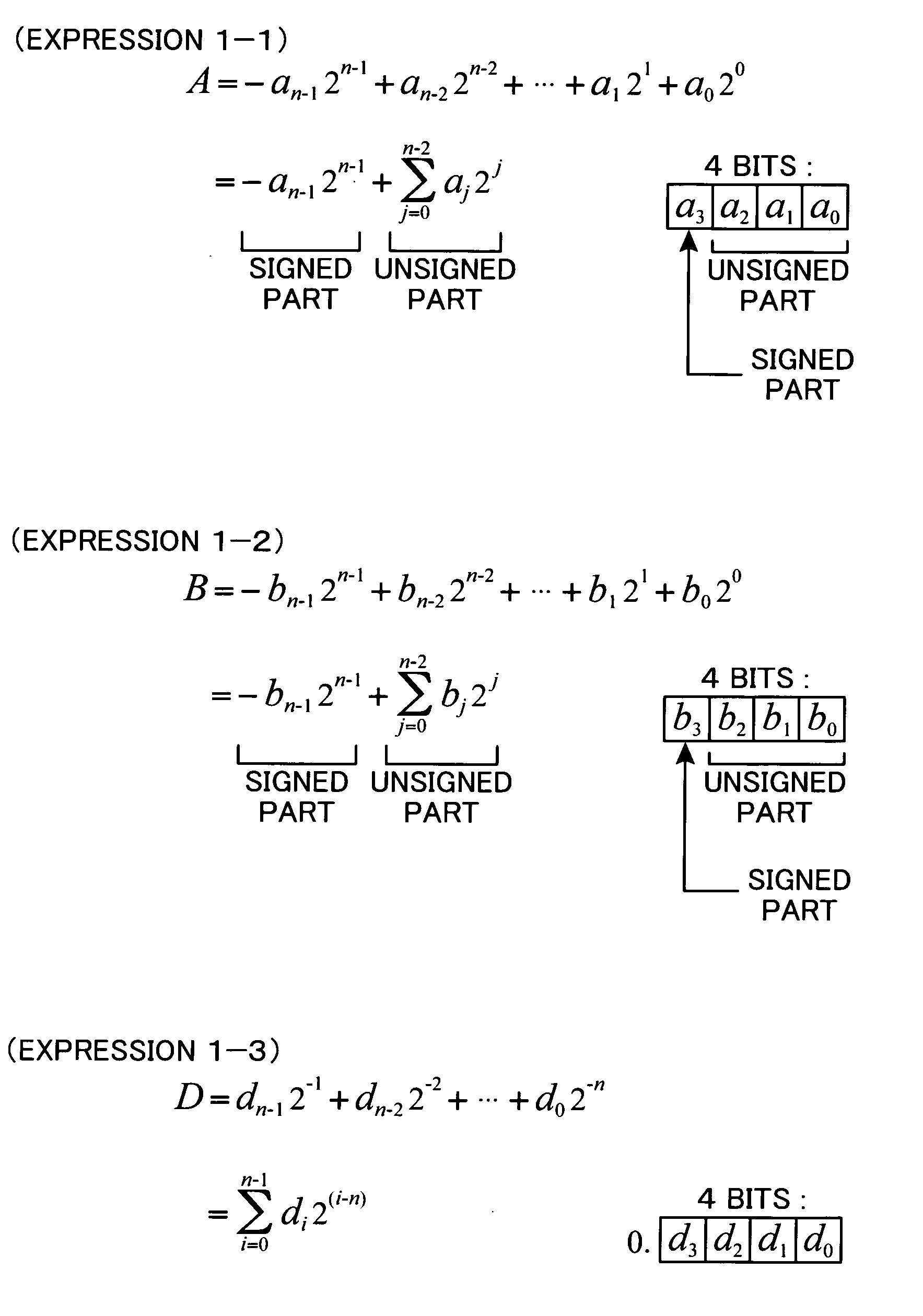
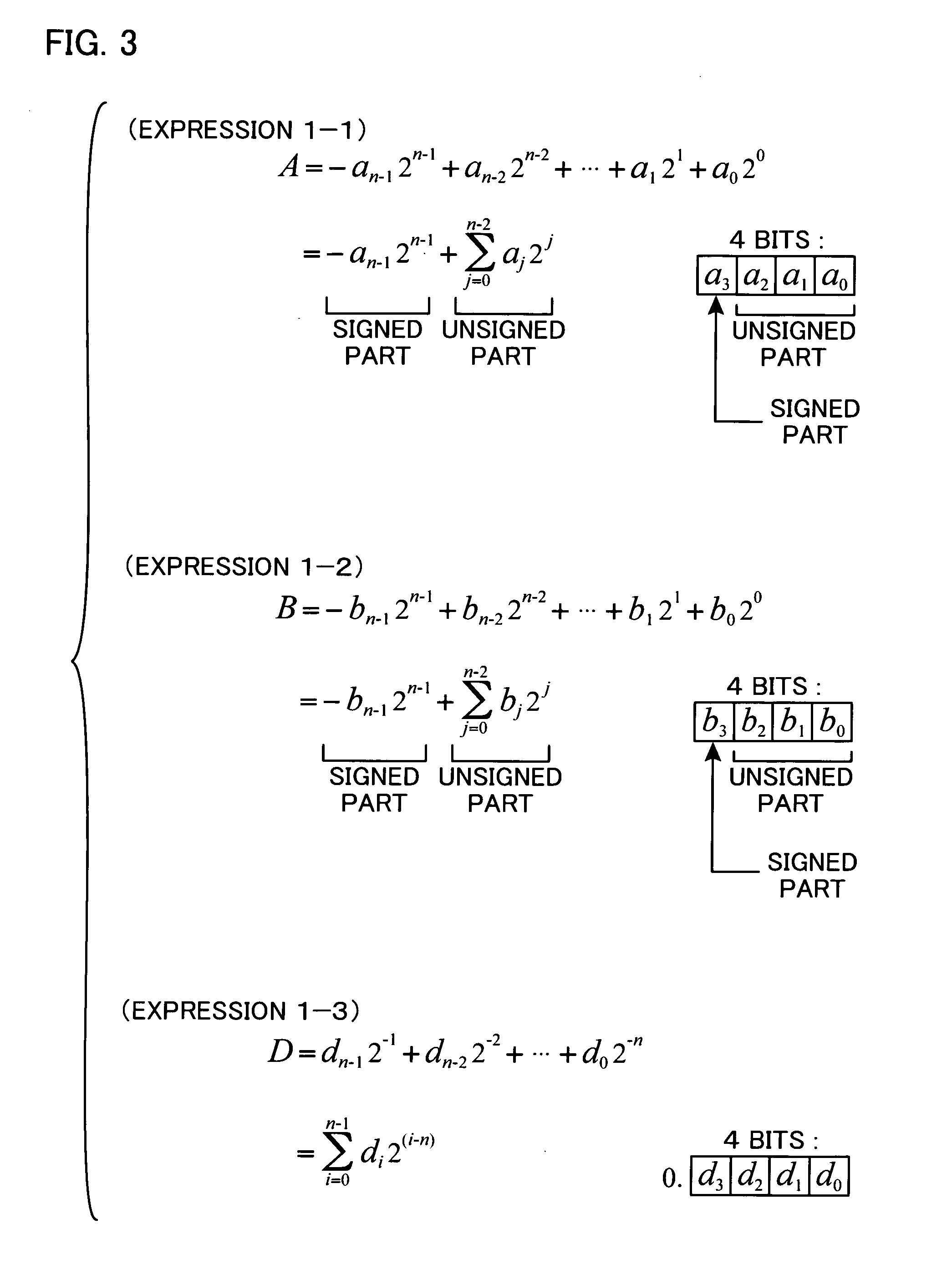
[0195] Here, an embodiment illustrating a first aspect of the invention will be described. The first aspect of the invention proposes a technique for efficiently executing linear interpolation of two signed interpolation target values by a simple constitution.

>>

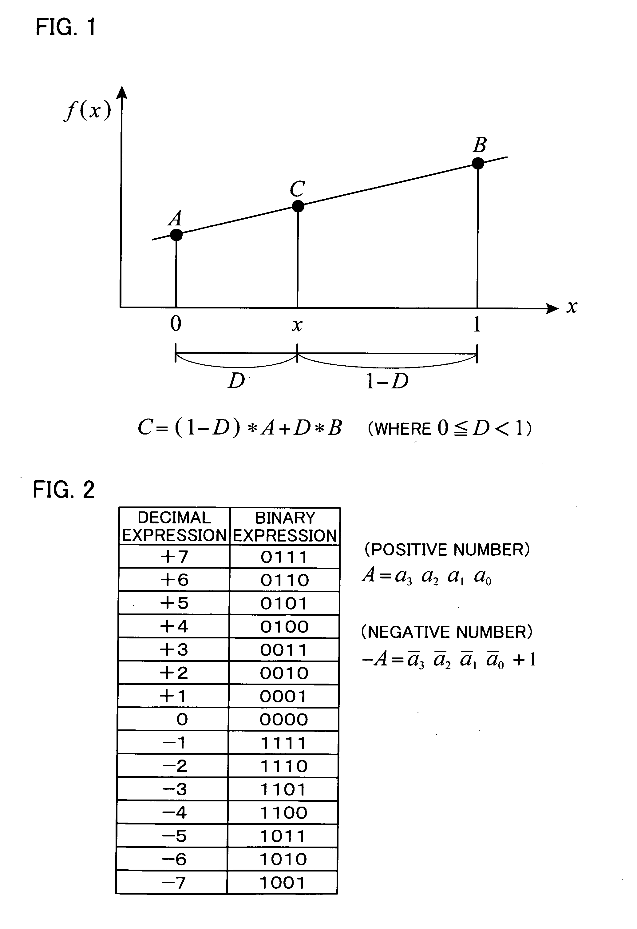
[0196] First, a basic concept of general linear interpolation and general negative number expression in digital data will be briefly described. FIG. 1 is a graph showing a basic concept of linear interpolation. In the illustrated example, an interval 0-1 is set on the X axis and a method for calculating a function value at an arbitrary position x in the interval 0-1 when a value of the function f(x) is defined only at both ends of the interval is shown. In detail, when f(0)=A and f(1)=B, a value of a function f(x)=C about arbitrary x in the range of 0≦x≦1 is calculated by interpolation using values A and B.

[0197] In linear interpolation, as illustrated, a straight line ...


PUM


Abstract

Interpolation of signed values A and B is efficiently performed by simple circuitry. To calculate an interpolated value C based on a 4-bit values A (bits a3a2a1a0) and B (bits b3b2b1b0) expressing a negative number by twos complement notation and a 4-bit interpolation rate D (bits d3d2d1d0) consisting of only a decimal part, a basic expression of C=(1−D)*A+D*B is transformed into an expression composed of an unsigned part that includes a sum of products with a bit di or a logically inverted value ei of the bit di (i=0, 1, 2, and 3), and indicates an absolute value of the interpolated value C, and a signed part indicating a sign of the interpolated value C. Then, 7 bits of bits c6 through c0 are generated from an arithmetic operation of the unsigned part, and logic judgement of the signed part is performed by considering a carry from the digit of the bit c6 of the arithmetic operation of the unsigned part to generate a bit c7. Significant digits of the obtained 8-bit value (bits c7 through c0) are outputted as an interpolated value.

Description

BACKGROUND OF THE INVENTION [0001] The invention disclosed in the present application relates to a linear interpolator and a designing method thereof. More specifically, the present invention relates to a technique for calculating a linear interpolated value of two signed interpolation target values by a hardware circuit, and to a technique for realizing a simple hardware circuit which can calculate a high-accuracy linear interpolated value. [0002] As a method for obtaining an intermediate value of two values by means of interpolation, linear interpolation is most representative. Recently, in particular, as a method for image processing, this linear interpolation is popularly utilized. For example, the method for image synthesis generally called “α-blend” is a method in which an image A and an image B are synthesized at a ratio of α:(1−α)(0≦α≦1), and processing for obtaining an intermediate value of a pixel value of the image A and a pixel value of the image B by means of linear int...

Claims


Application Information

Patent Timeline
IPC IPC(8): G06F7/38
CPCG06F7/544
Inventor TONOMURA, MOTONOBUYOSHINO, KYOUJI
Owner DAI NIPPON PRINTING CO LTD
Why Eureka
Try Eureka