Cogeneration system

a cogeneration system and system technology, applied in the direction of machines/engines, engine components, mechanical equipment, etc., can solve the problems of increased cost, leakage of exhaust gas, and inability to shift the bypass damper, so as to increase the reliability of the system

Inactive Publication Date: 2007-06-21
TAKUMA
View PDF1 Cites 7 Cited by
  • Summary
  • Abstract
  • Description
  • Claims
  • Application Information

AI Technical Summary

Benefits of technology

[0010] According to the invention, since the bypass damper provided for the inlet of the bypass path is controlled so as to be opened and closed by the air cylinder driven by compressed air fed from the compressor, the bypass damper can be always switched to a proper direction by making use of the compressed air even if a supply of electric power is cut off in an abnormal state or the like. Therefore, troubles due to the bypass damper which becomes unswitchable can be avoided. In addition, since the bypass damper can be constantly pressed in a specified direction unlike the systems which use an electric motor, the problem of leakage of exhaust gas can be overcome. Even if the system of the invention uses a large-sized bypass damper, the peripheral devices do not change in size although the air cylinder body becomes slightly large and therefore the system of the invention can be manufactured at lower cost compared to the systems which use an electric motor.
[0012] In the above arrangement, use of the check valve reliably prevents a reverse flow of the compressed air even in the case of an emergency stop of the gas turbine etc. Use of the accumulator ensures a sufficient amount of air for driving the air cylinder, even when the pressure of the compressed air from the compressor is insufficient, for instance, in the case of an emergency stop of the gas turbine.
[0014] Thus, even if the direction control valve for switching the direction of the compressed air to be supplied to the air cylinder is de-energized, the bypass damper can be switched to a safe direction to close the path on the side of the exhaust-heat-recovery heat exchanger and to open the bypass path, so that the reliability of the system can be more increased.

Problems solved by technology

However, the systems designed to drive the bypass damper with an electric motor like the above conventional system suffers from the problem that the bypass damper cannot be shifted if a supply of electric power to the electric motor is shut off, for instance, when an abnormality arises.
These systems, however, present the drawback that since the motor shaft is not completely fixed, a clearance is created between the valve disc and the valve sheet by the wind force of exhaust gas, the elasticity of the bypass damper or the like, resulting in a leakage of exhaust gas.
In the above conventional systems, as the bypass damper increases in size, the torque required to operate the damper increases, so that there arises a need for a large-sized electric motor, which inevitably leads to increased cost.

Method used


Image

  • Cogeneration system
  • Cogeneration system
  • Cogeneration system

Examples


Embodiment Construction

[0019] Referring now to the accompanying drawings, concrete embodiments of the invention will be described.

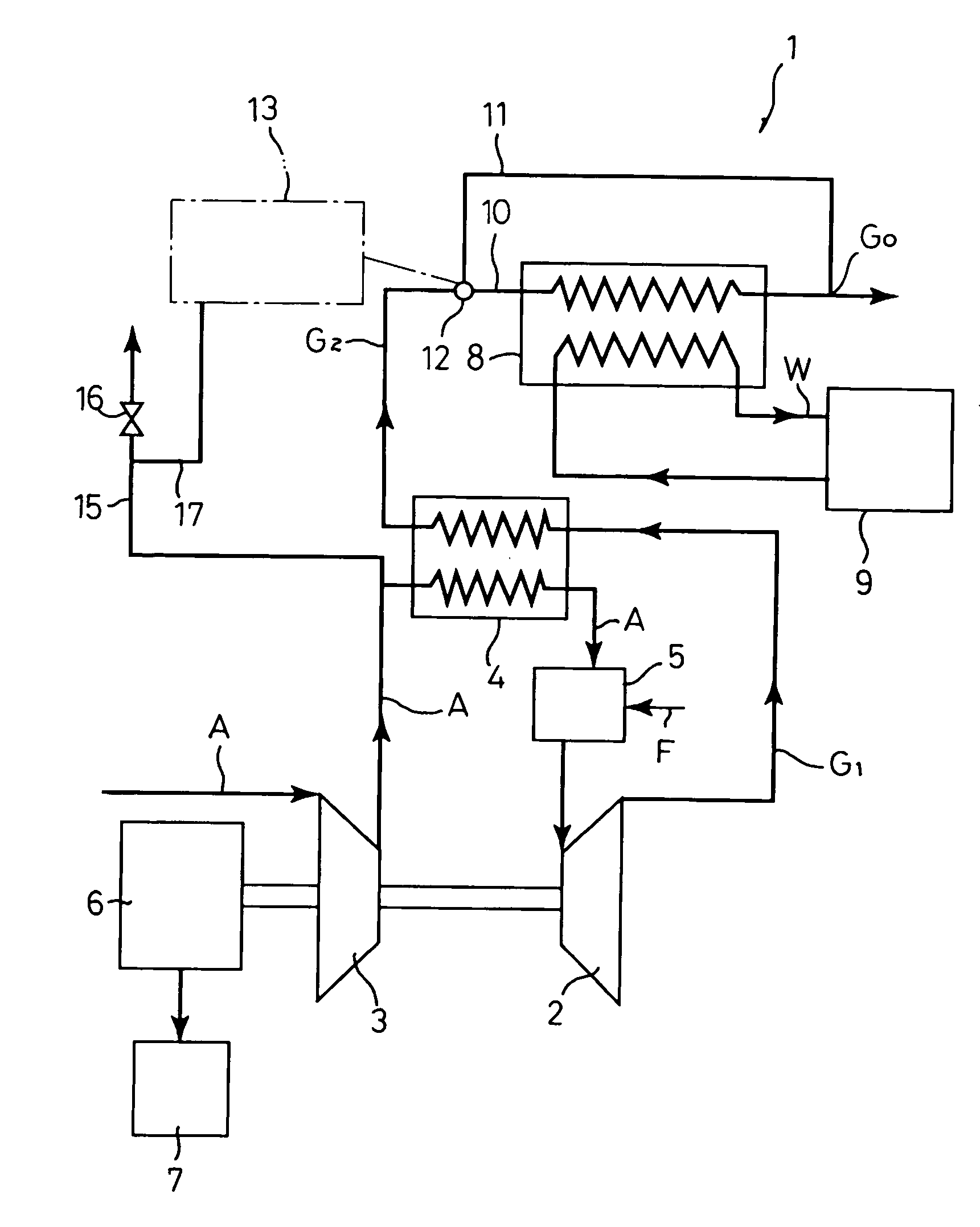
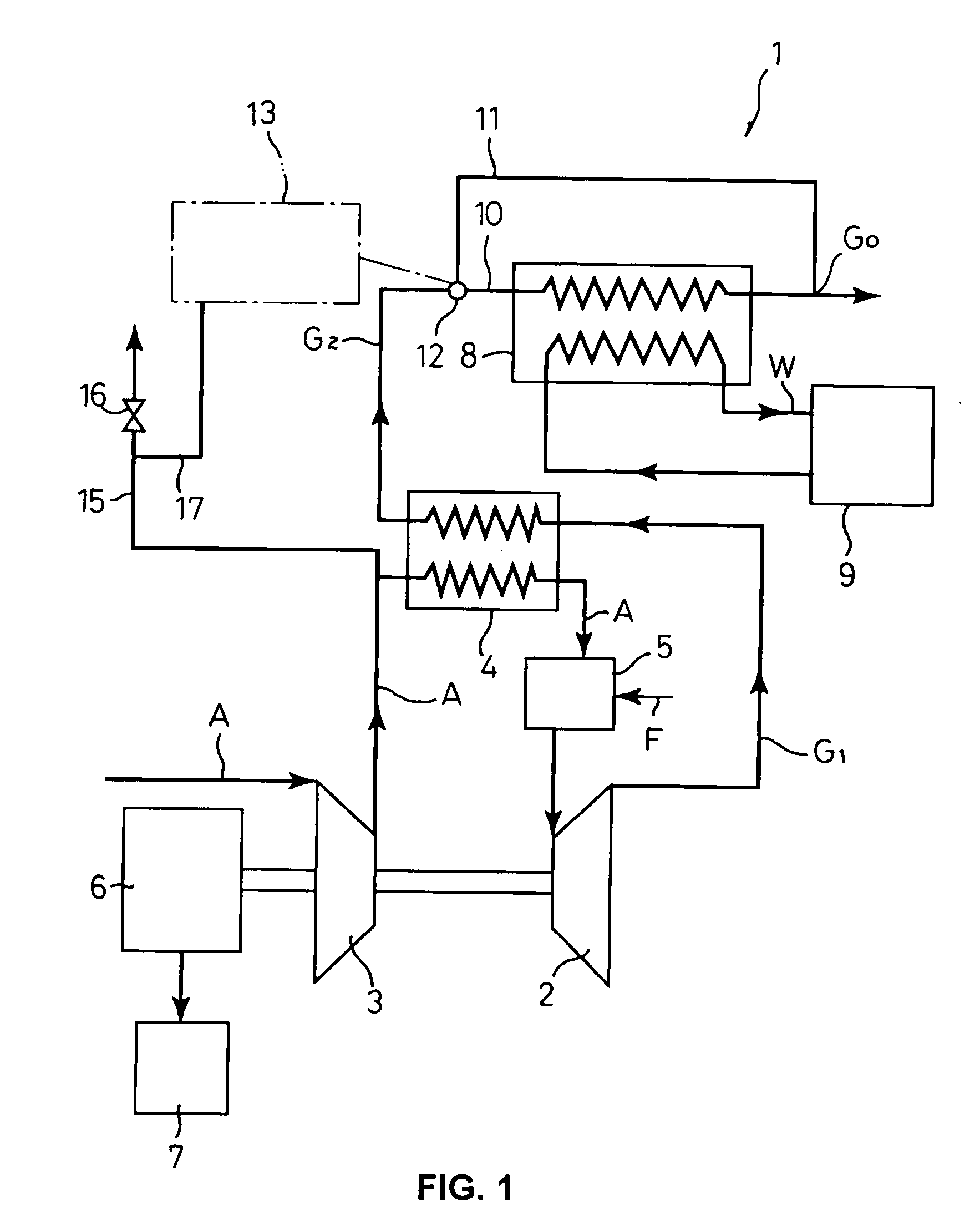
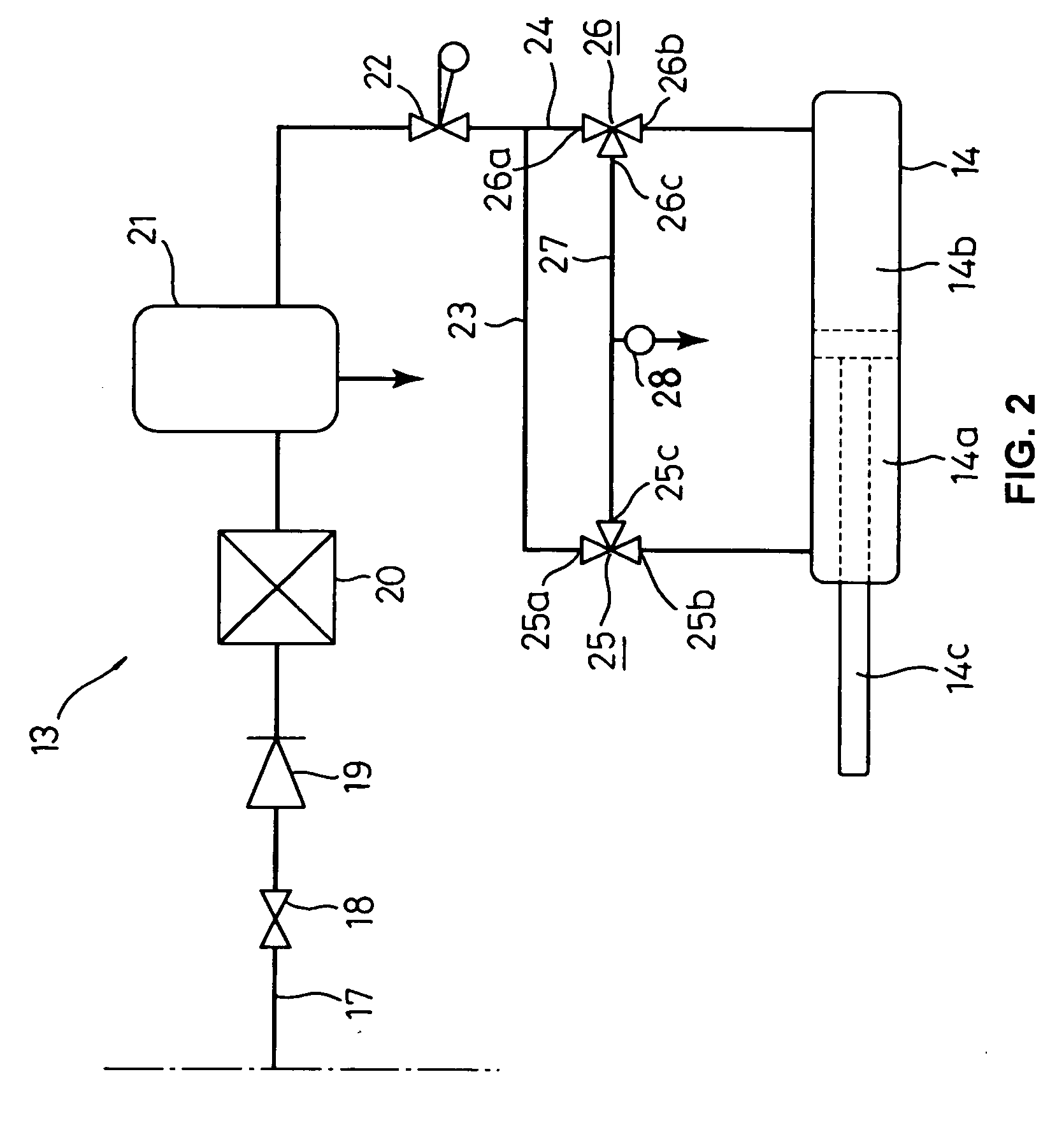
[0020]FIG. 1 shows a system structural diagram showing a micro gas turbine cogeneration system constructed according to one embodiment of the invention. FIG. 2 shows a circuit diagram of an air cylinder driving circuit for driving a bypass damper.

[0021] In the cogeneration system 1 of the first embodiment, combustion air A is supplied to and pressurized by a compressor 3 directly connected to a gas turbine 2 and then, supplied to a combustion chamber 5 through a recuperator 4. In the recuperator 4, the combustion air (compressed air) A is heat-exchanged with an outlet gas (high-temperature exhaust gas) G1 of the gas turbine 2, whereby the combustion air A is preheated. In the combustion chamber 5, the combustion air A preheated by the recuperator 4 and a fuel gas F to be supplied to the combustion chamber 5 are mixed and burnt so that high-temperature combustion gas is genera...


PUM


Abstract

A cogeneration system is provided which is capable of reliably switching a bypass damper even if a supply of electric power is shut off in an abnormal state etc. and which is unlikely to leak exhaust gas and is cost-effective even if it is increased in size. To this end, an exhaust gas path (10) for introducing exhaust gas from a gas turbine (2) into an exhaust-heat-recovery heat exchanger (8) is provided with a bypass path (11) and an inlet of the bypass path (11) is provided with a bypass damper (12) which is controlled so as to be opened and closed by an air cylinder driven by compressed air from the compressor (3).

Description

TECHNICAL FIELD [0001] The present invention relates to a cogeneration system (heat / electricity joint supplying system) for supplying electric power and hot water or the like at the same time, using a gas turbine generator and an exhaust-heat-recovery heat exchanger in combination. BACKGROUND ART [0002] There have been known and practically used cogeneration systems (heat / electricity joint supplying systems) which generate electric power by a gas turbine generator and generate hot water etc. by recovering the heat of high-temperature exhaust gas from the gas turbine with an exhaust-heat-recovery exchanger. Of the systems of this type, systems having a relatively small capacity of about 15 to 300 KW are utilized as a micro gas turbine cogeneration system (see Japanese Patent Published Unexamined Application No. 2002-4945). [0003] In one known cogeneration system of the above type, an exhaust gas path for introducing the exhaust gas of the gas turbine into the exhaust-gas-recovery hea...

Claims


Application Information

Patent Timeline
Patent Type & Authority Applications(United States)
IPC IPC(8): F02C6/04F02C6/18F01D17/00F02C7/08F02C9/18F02G5/02F02G5/04
CPCF02C6/18F02C7/08F02G5/02Y02E20/14Y02T10/166Y02T10/12
Inventor KISHIDA, HIROYUKISHIRAGAKI, MAMORUSHIBATA, SATOSHI
Owner TAKUMA
Why Eureka
Try Eureka