Drive arrangement for motorized actuation of a functional element in a motor vehicle

a technology for motor vehicles and functional elements, which is applied in the direction of gearing, hoisting equipment, roofs, etc., can solve the problems of large extension of the drive arrangement, large installation space in the interior of the vehicle, and considerable length of the spindle-spindle nut gear in the retracted state, so as to reduce the required installation space and optimize the design layout. , the effect of low construction effor

Inactive Publication Date: 2007-06-21
BROSE SCHLIESSSYSTEME GMBH & CO KG
View PDF7 Cites 50 Cited by
  • Summary
  • Abstract
  • Description
  • Claims
  • Application Information

AI Technical Summary

Benefits of technology

[0008] A primary object of the invention is to embody and develop the known drive arrangement such that, with low construction effort, the required installation space is reduced and the design layout is optimized.

Problems solved by technology

The disadvantage in the known drive arrangement is that the spindle-spindle nut gear has a considerable length in the retracted state.
This costs installation space in the interior of the vehicle which is fundamentally dimensioned to be tight.
The large extension of the drive arrangement is also a problem in terms of aesthetics.
However, it can also be that these gas pressure dampers are not provided, so that the expenditure of force necessary for the opening motion is maximum when the hatch is almost completely opened.
This compromise leads to high costs since the drive motor is over-dimensioned for a considerable part of the positioning motion of the rear hatch.

Method used


Image

  • Drive arrangement for motorized actuation of a functional element in a motor vehicle
  • Drive arrangement for motorized actuation of a functional element in a motor vehicle
  • Drive arrangement for motorized actuation of a functional element in a motor vehicle

Examples


Embodiment Construction

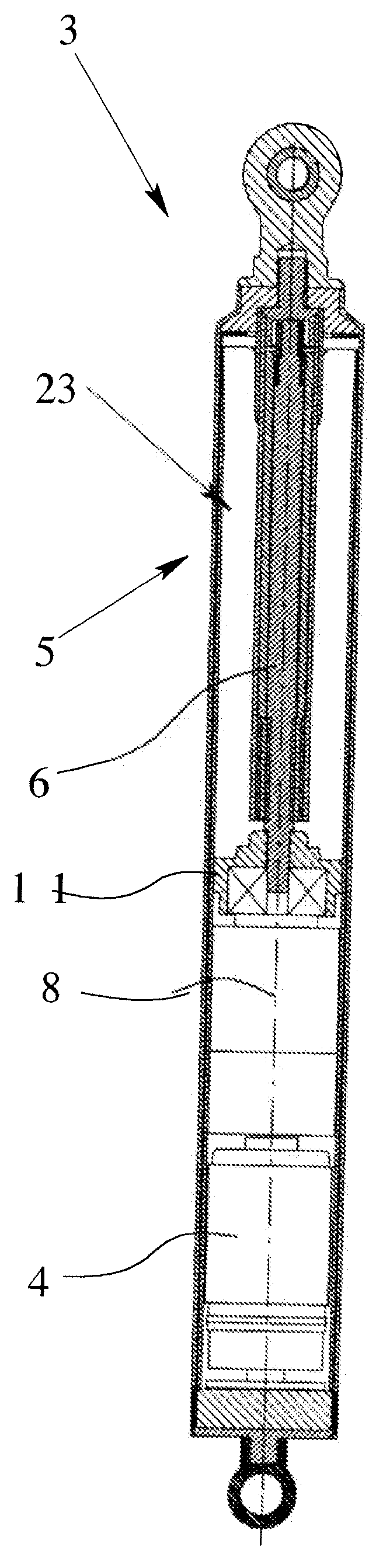
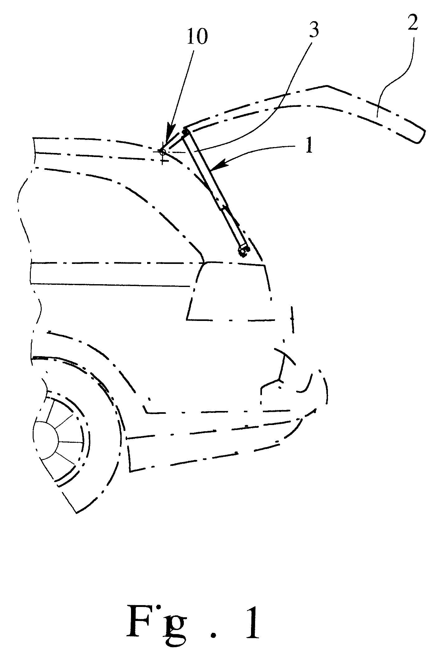
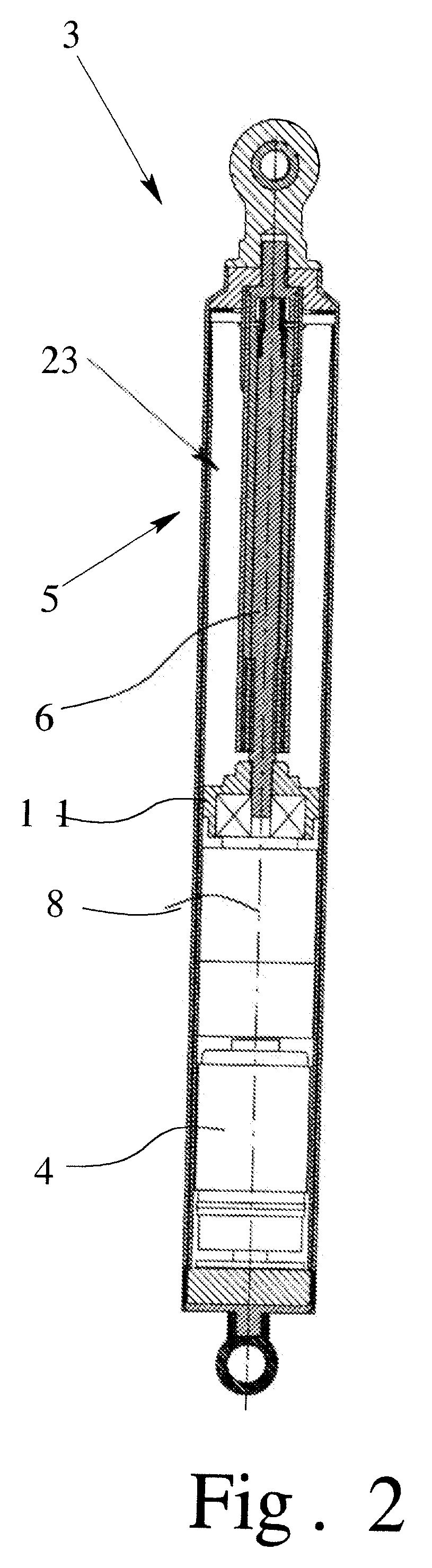
[0024] The motor vehicle shown in FIG. 1 has a drive arrangement for motorized actuation of a functional element 2 in the form of a rear hatch with a drive 3. The drive 3 (shown in FIG. 3) is equipped with a drive motor 4 and a spindle-spindle nut gear 5 connected downstream of the drive motor 4 for producing linear drive movements. The spindle-spindle nut gear 5 has a spindle 6 with an outside thread 6a and a spindle nut 7 with an inside thread 7a (FIG. 3). The linear drive motion is provided by motion of the spindle nut 7 parallel to the spindle axis 8, as is fundamentally conventional in spindle-spindle nut gears.

[0025] The spindle-spindle nut gear 5, as compared to known spindle-spindle nut gears, is a modified arrangement in that there is at least one telescoping sleeve 9, here, with an inside thread 9a and an outside thread 9b, which is connected between the spindle 6 and the spindle nut 7. This is apparent when FIGS. 2 & 3 are viewed together. Here, it is such that the spind...


PUM


Abstract

Drive arrangement for motorized actuation of a functional element in a motor vehicle, having at least one drive, the drive having a drive motor and a spindle-spindle nut gear connected downstream of the drive motor for producing linear drive movements, the spindle-spindle nut gear having a spindle with an outside thread and a spindle nut with an inside thread, the linear drive movements being a motion of the spindle nut parallel to a spindle axis. the spindle-spindle nut gear has at least one telescoping sleeve with an inside thread and an outside thread. The at least one telescoping sleeve, spindle and spindle nut are arranged in a telescoping manner being screwed into one another with each outside thread forming a thread pairing with an respective inside thread. An alternative spindle-spindle nut gear has the outside thread and form a ball groove thread pairing with a variable thread pitch.

Description

BACKGROUND OF THE INVENTION [0001] 1. Field of the Invention [0002] The invention relates to a drive arrangement for motorized actuation of a functional element in a motor vehicle with at least one drive, the drive having a drive motor and a spindle-spindle nut gear connected downstream of the drive motor for producing linear drive movements, the spindle-spindle nut gear having a spindle with an outside thread and a spindle nut with an inside thread, and the linear drive motion being moving the spindle nut parallel to the spindle axis. [0003] 2. Description of Related Art [0004] Within the framework of enhancing the ease of operation in motor vehicles, drive arrangements of the type under consideration are becoming more and more important. The functional elements which can be moved by a motor here are, for example, hatches, especially rear hatches, rear covers, side doors or lifting roofs, vehicle seats or the like. In addition to high reliability and low costs, the compactness of s...

Claims


Application Information

Patent Timeline
Patent Type & Authority Applications(United States)
IPC IPC(8): F16H27/02F16H29/02
CPCE05Y2800/122E05Y2900/546F16H25/2056E05F15/622Y10T74/18568Y10T74/19744Y10T74/18672Y10T74/18576
Inventor KACHOUH, CHECRALLAH
Owner BROSE SCHLIESSSYSTEME GMBH & CO KG
Why Eureka
Try Eureka