Methods and apparatus for conditioning and degassing liquids and gases in suspension

a technology of liquid and gas suspension, which is applied in the field of methods and apparatus for conditioning mixtures of gas and liquids, can solve the problems of affecting the separation function, so as to improve the performance of downstream separators, increase the local concentration of dispersion and the chance of droplet interaction

Active Publication Date: 2007-06-21
SCHLUMBERGER TECH CORP
View PDF6 Cites 24 Cited by
  • Summary
  • Abstract
  • Description
  • Claims
  • Application Information

AI Technical Summary

Benefits of technology

[0011] In a first aspect of the invention, there is provided coalescing apparatus for increasing the droplet size of a mixture formed as a liquid dispersed in another liquid comprising an ultrasonic transducer arranged to impart vibrational energy preferably in the frequency range 200 kHz to 1.5 MHz and more particularly in the range 400 kHz-1.5 MHz, to the mixture and a reflector located generally opposite the transducer, the apparatus further including at least one baffle extending in a direction generally between the transducer and the reflector and which divides the space between the transducer and reflector into separate volumes, the baffles being arranged in use to be sufficiently rigid to generally prevent substantial fluid flow between the volumes.
[0012] This provides the controlled application of ultrasonic energy in the form preferably of a resonant standing wave to generate coalescence in a dispersion (which may be static or flowing) of one liquid in another where separation of the liquid phases is a process objective. Differences in acoustic properties between the liquids allows the imposed acoustic radiation force to drive the droplets to the nodes or antinodes of the standing wave, thereby increasing local concentrations of the dispersion and the chances of droplet interaction. The coalescence this achieves provides a basis for improved performance of downstream separators, the efficiencies of which are generally strongly dependent on drop size.

Problems solved by technology

Separation of water from a predominantly oil stream or treatment of a water stream to remove oil is generally more difficult and expensive as the droplet size of the dispersed, minority phase decreases.
Foaming is deleterious to the separation function since it may, for example, fill process equipment.
Furthermore, foaming can lead to false readings on apparatus such as level detectors in vessels.
However, the applicant's research has shown that the configuration disclosed in this document is unlikely to succeed as the fluid velocities typically encountered in pipeflow are too high and the flow is too turbulent for the ultrasonic forces to be effective.
Also the residence in the field of the transducers is too short.
Such techniques, in the case of electrostatic coalescers are not effective on water continuous-mixtures, or in the case of filter coalescers have limitations due to the likelihood of blockage.

Method used


Image

  • Methods and apparatus for conditioning and degassing liquids and gases in suspension
  • Methods and apparatus for conditioning and degassing liquids and gases in suspension
  • Methods and apparatus for conditioning and degassing liquids and gases in suspension

Examples


Embodiment Construction

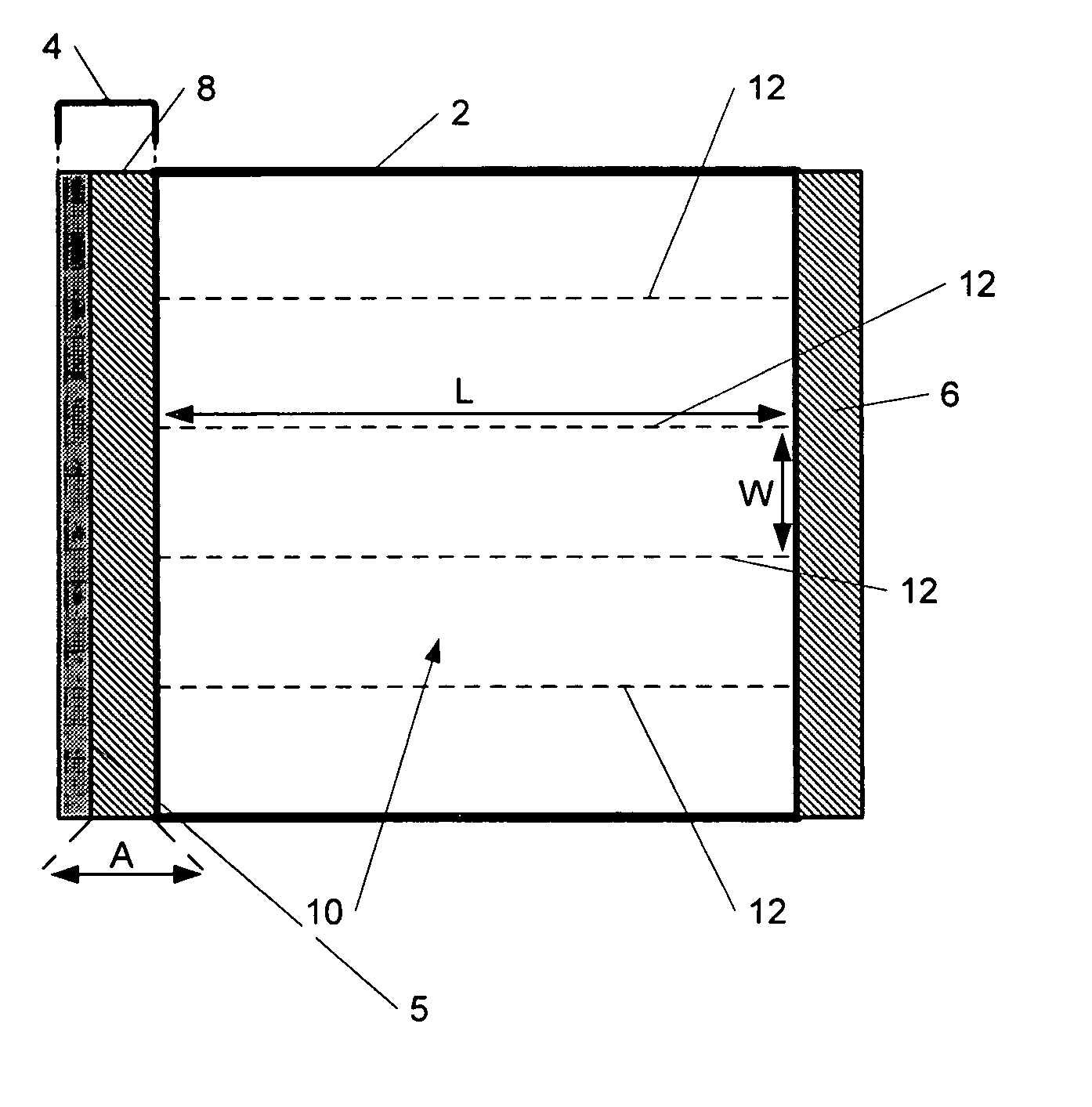
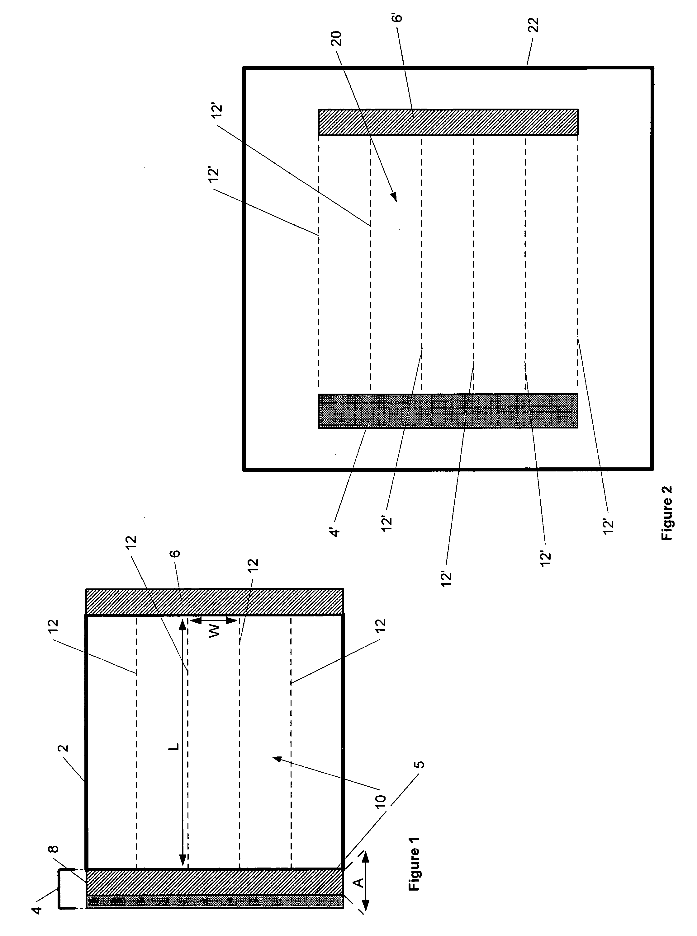
[0028] With reference to FIG. 1, a generally square section vessel 2 has a transducer 4 mounted along one side and a reflector 6 mounted on the opposite side of the vessel 2. The transducer 4 is typically formed as a piezoelectric layer 5 which converts an oscillating electrical voltage applied across the layer into a corresponding mechanical vibration, with an optional carrier 8. Typically, the layer 5 is made from a piezoceramic material.

[0029] The transducer 4 is optionally coupled to the vessel 2 by a carrier 8 which effectively provides impedance matching between the transducer and the vessel wall. The carrier 8 represents an electrically insulative layer which isolates the piezoceramic layer 5 from the liquid. Its thickness and acoustic impedance are important for achieving efficient transmission of acoustic energy into the vessel 2. However, in some applications and including the other embodiments described below, the transducer 4 may be mounted directly to the wall of the v...


PUM

PropertyMeasurementUnit
distanceaaaaaaaaaa
distanceaaaaaaaaaa
frequencyaaaaaaaaaa

Abstract

A method and apparatus are provided for the controlled application of ultrasonic energy for conditioning of mixtures of gas and liquids by evolving and/or agglomerating gas bubbles existing with or in a liquid or for coalescing droplets of liquid dispersed in another liquid. The invention in preferred embodiments thereof comprises a coalescing apparatus for Increasing the droplet size of a mixture formed as a liquid dispersed in another liquid, and a de-gassing apparatus arranged to evolve and/or agglomerate gaseous bubbles in a gas/liquid mixture. In the apparatuses, ultrasonic transducers are used to impart vibrational energy to the mixtures.

Description

FIELD OF THE INVENTION [0001] This invention relates to methods and apparatus for conditioning mixtures of gas and liquids by agglomerating gas bubbles existing with or in a liquid or for coalescing droplets of liquid dispersed in another liquid. BACKGROUND OF THE INVENTION [0002] Liquids produced in oilfield applications comprise a hydrocarbon component, (which may be a low density oil, termed condensate, or a medium density oil, termed medium oil or a high density oil, termed heavy oil) and some accompanying water which may be naturally occurring with the oil or may have been pumped into the reservoir to help drive out the oil. In order to process the oil successfully, the water must be separated out allowing relatively dry oil to be exported. In turn the water itself must be treated to an acceptable content of oil suitable for disposal. [0003] Separation of water from a predominantly oil stream or treatment of a water stream to remove oil is generally more difficult and expensive...

Claims


Application Information

Patent Timeline
Patent Type & Authority Applications(United States)
IPC IPC(8): C02F1/36
CPCB01D17/044B01D19/0078C02F1/20C02F1/36C02F2101/32
Inventor HADFIELD, DAVIDSINKER, ALASTAIRSMYTH, IAN CHARLES
Owner SCHLUMBERGER TECH CORP
Why Eureka
Try Eureka