Coalescer For Co-Current Contactors

a co-current contactor and co-current technology, applied in the direction of gaseous fuels, gaseous mixtures working up, separation processes, etc., can solve the problems of affecting the operation of the co-current contactor,

Active Publication Date: 2016-09-15
EXXONMOBIL UPSTREAM RES CO
View PDF3 Cites 23 Cited by
  • Summary
  • Abstract
  • Description
  • Claims
  • Application Information

AI Technical Summary

Benefits of technology

[0014]The disclosure includes a co-current contactor apparatus, comprising a first inlet configured to receive a first fluid stream proximate to a first end of the co-current contactor, a second inlet configured to receive a second fluid stream proximate to the first end of the co-current contactor, an inlet section configured to atomize at least a portion of the second fluid stream, a mass transfer section configured to receive the first fluid stream and the atomized second fluid stream, and to pass the atomized second fluid stream and the first fluid stream as a combined stream, a coalescer configured receive the combined stream, and to increase an average droplet size of the atomized second fluid stream, and a separator configured to separate at least a portion of the atomized second fluid stream from the combined stream.

Problems solved by technology

Indeed, water is the most common contaminant in many natural gas streams.
The formation of gas hydrates and corrosion in pipelines can cause a decrease in flow volume as well as frozen control valves, plugged orifices and other operating problems.
While perhaps capable of performing desired contacting for removal of contaminants from a gas and / or hydrocarbon-containing fluid stream, historic contactor designs have had difficulty scaling-up from lab and / or pilot-sized units to units capable of efficiently processing up to a billion standard cubic feet per day (BSFD) of gas.
Past scale-up designs have high capital expenses (e.g., due to having larger and more pieces of equipment, more complicated transportation and installation, etc.) and high operational expenses (e.g., due to less reliability and / or operability, larger size and weight equipment, etc.).

Method used


Image

  • Coalescer For Co-Current Contactors
  • Coalescer For Co-Current Contactors
  • Coalescer For Co-Current Contactors

Examples


Embodiment Construction

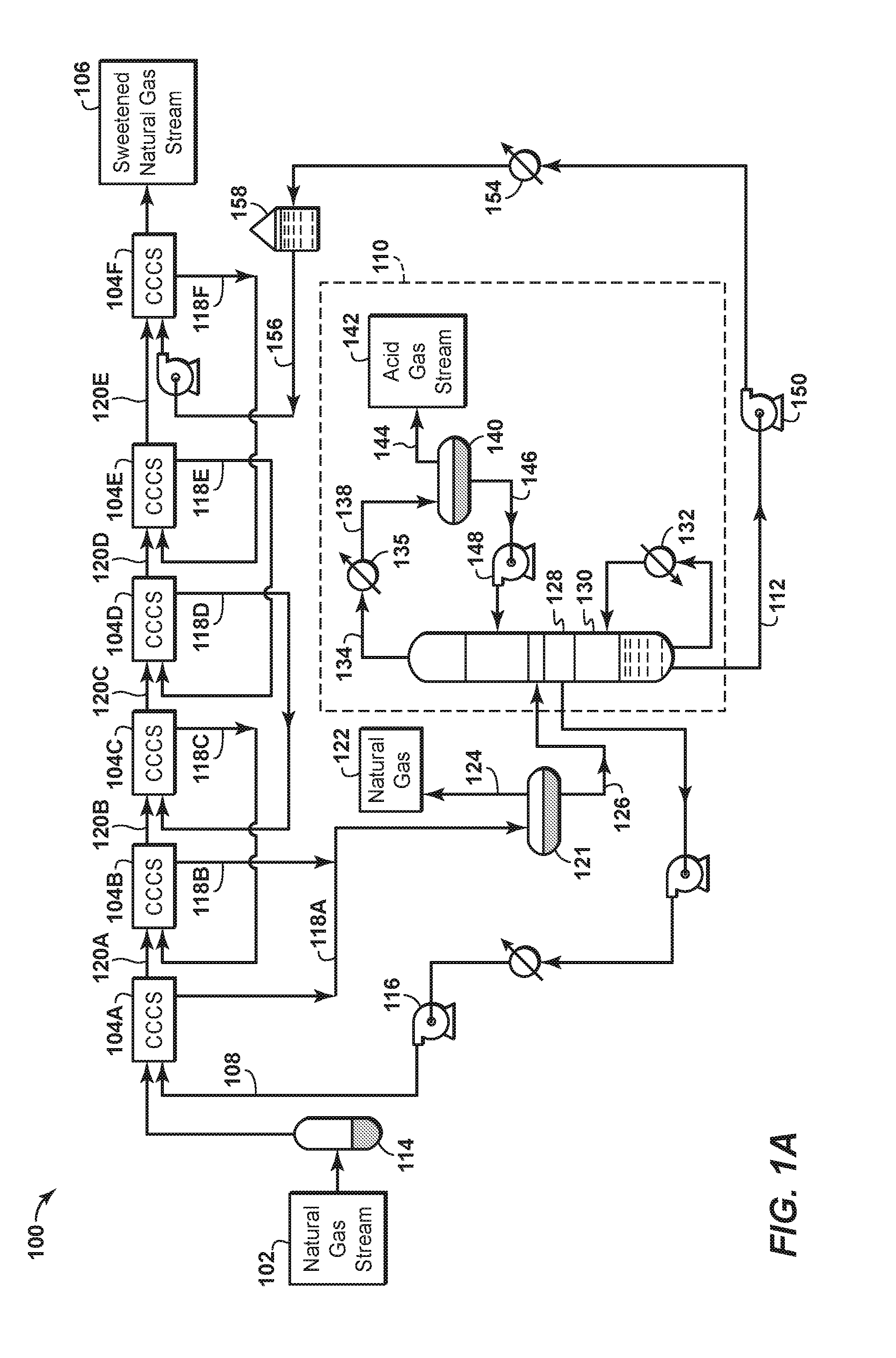
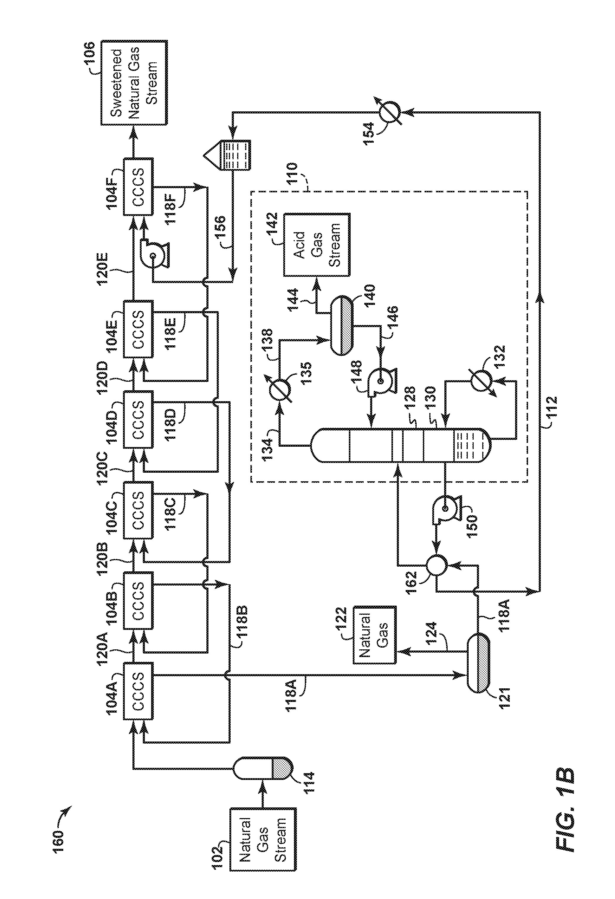
[0023]As used herein, an “acid gas” means any gas that dissolves in water producing an acidic solution. Non-limiting examples of acid gases include hydrogen sulfide (H2S), carbon dioxide (CO2), sulfur dioxide (SO2), carbon disulfide (CS2), carbonyl sulfide (COS), mercaptans, or mixtures thereof.

[0024]As used herein, the term “atomize” means to divide, reduce, or otherwise convert a liquid into minute particles, a mist, or a fine spray of droplets having an average droplet size within a predetermined range.

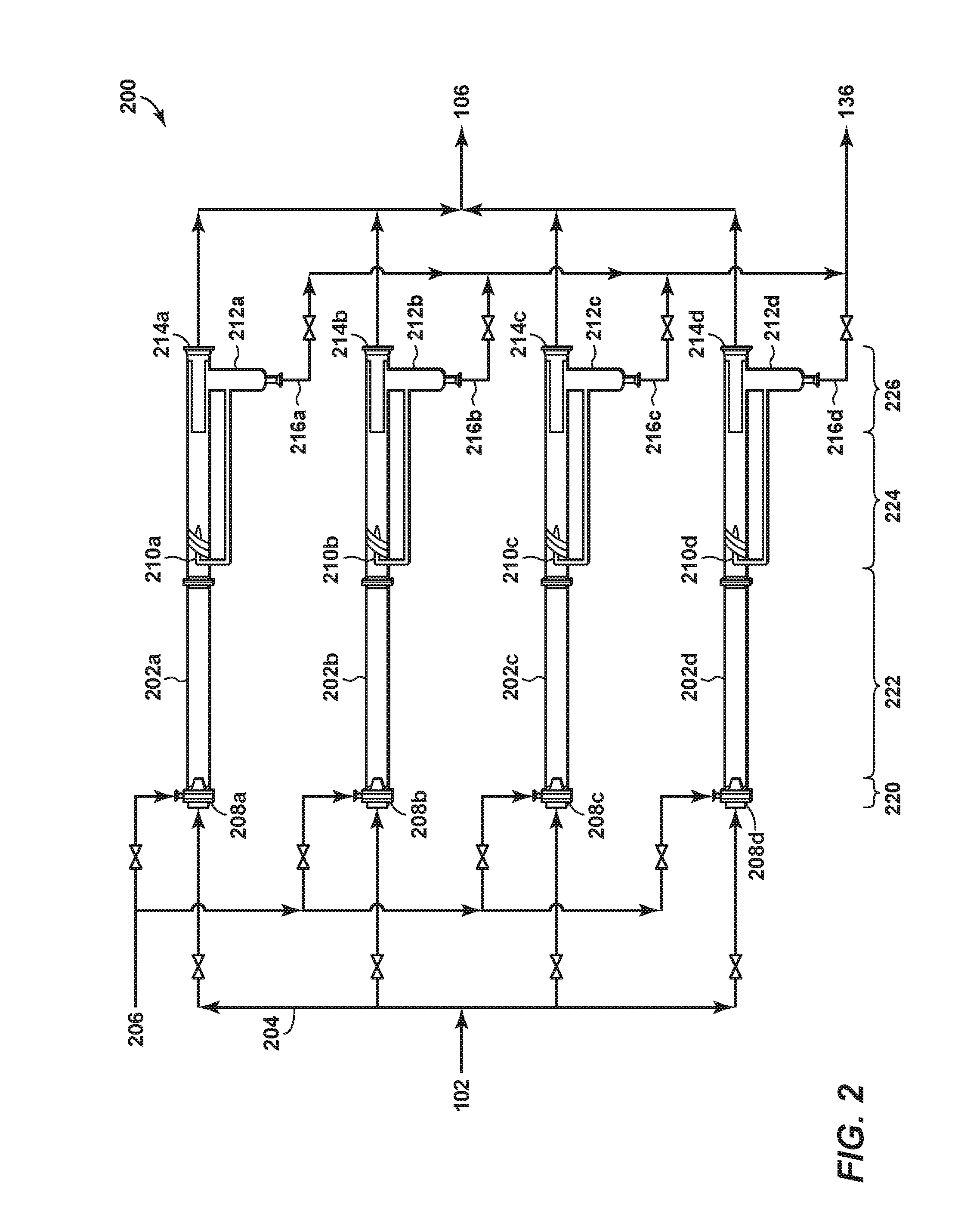
[0025]As used herein, the term “co-current contacting device” or “co-current contactor” means an apparatus, e.g., a pipe, a vessel, a housing, an assembly, etc., that receives (i) a stream of gas (or other fluid stream to be treated) and (ii) a separate stream of solvent (or other fluid treating solution) in such a manner that the gas stream and the solvent stream contact one another while flowing in generally the same direction within the contacting device.

[0026]As used herein, th...


PUM

PropertyMeasurementUnit
droplet sizeaaaaaaaaaa

Abstract

The disclosure includes a method, comprising passing a fluid into a co-current contactor, passing a solvent into the co-current contactor, dividing the solvent into solvent droplets having a first average droplet size, placing the fluid in contact with the solvent droplets to create a combined stream, coalescing at least a portion of the solvent droplets to create solvent droplets having a second average droplet size, wherein the second average droplet size is greater than the first average droplet size, and separating the fluid and the solvent.

Description

CROSS REFERENCE TO RELATED APPLICATIONS[0001]This application claims the priority benefit of U.S. Patent Application 62 / 132,631 filed Mar. 13, 2015 entitled COALESCER FOR CO-CURRENT CONTACTORS, the entirety of which is incorporated by reference herein.BACKGROUND[0002]The production of hydrocarbons from a reservoir oftentimes carries with it the incidental production of non-hydrocarbon gases. Such gases include contaminants such as hydrogen sulfide (H2S) and carbon dioxide (CO2). When H2S or CO2 are produced as part of a hydrocarbon stream (such as methane or ethane), the raw gas stream is sometimes referred to as “sour gas.” The H2S and CO2 are often referred to together as “acid gases.”[0003]In addition to hydrocarbon production streams, acid gases may be associated with synthesis gas streams, or with refinery gas streams. Acid gases may also be present within so-called flash-gas streams in gas processing facilities. Further, acid gases may be generated by the combustion of coal, n...

Claims


Application Information

Patent Timeline
Patent Type & Authority Applications(United States)
IPC IPC(8): B01D53/14B01D11/04C10L3/10B01D53/79B01D53/52
CPCB01D53/1406B01D53/79B01D53/526C10L3/103C10L3/104B01D53/1475B01D2011/005B01D53/1462B01D11/04B01D11/0488B01D11/0419C10L2290/18C10L2290/541B01D53/1468B01D53/18C10L3/10C10G21/00B01D2252/204B01D2257/504B01D2257/304C10G21/16C10G21/30C10G70/06C10G2300/207
Inventor FREEMAN, STEPHANIE A.GRAVE, EDWARD J.CULLINANE, J. TIMNORTHROP, P. SCOTTYEH, NORMAN K.
Owner EXXONMOBIL UPSTREAM RES CO
Why Eureka
Try Eureka