Partial discharge detection apparatus and detection method of electrical rotating machine

a detection apparatus and technology of an electrical rotating machine, applied in the direction of dynamo-electric machine testing, dielectric strength testing, instruments, etc., can solve the problems of dielectric breakdown, machine malfunction, and progress of electrical insulation degradation inside the machine, and achieve high detection sensitivity and detection accuracy

Inactive Publication Date: 2007-06-21
KK TOSHIBA
View PDF6 Cites 52 Cited by
  • Summary
  • Abstract
  • Description
  • Claims
  • Application Information

AI Technical Summary

Benefits of technology

[0015] It is an object of the present invention to provide a partial discharge detection method and apparatus which enable easy attachment to a high-voltage unit in a noncontact state and ensure a high detection sensitivity and detection accuracy.

Problems solved by technology

When a high-voltage electrical rotating machine is continuously operated for a long time, degradation of electrical insulation inside the machine progresses due to electrical, thermal, mechanical, and environmental stress.
This may finally lead to dielectric breakdown and malfunction of the machine.
However, it is difficult to directly detect the partial discharge that has occurred in the coil inside an electrical rotating machine.
In this method, since the distance between a place at which the partial discharge occurs and the sensor is very short, the detection sensitivity is high, and detected noise may be small.
However, installation of the sensor must be done after the coil is removed, thereby being time-consuming.
In addition, attachment of the sensor is difficult.

Method used


Image

  • Partial discharge detection apparatus and detection method of electrical rotating machine
  • Partial discharge detection apparatus and detection method of electrical rotating machine
  • Partial discharge detection apparatus and detection method of electrical rotating machine

Examples


first embodiment

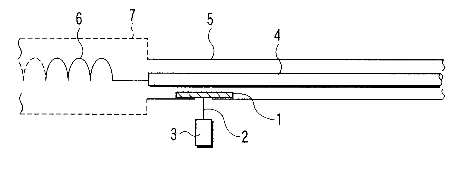
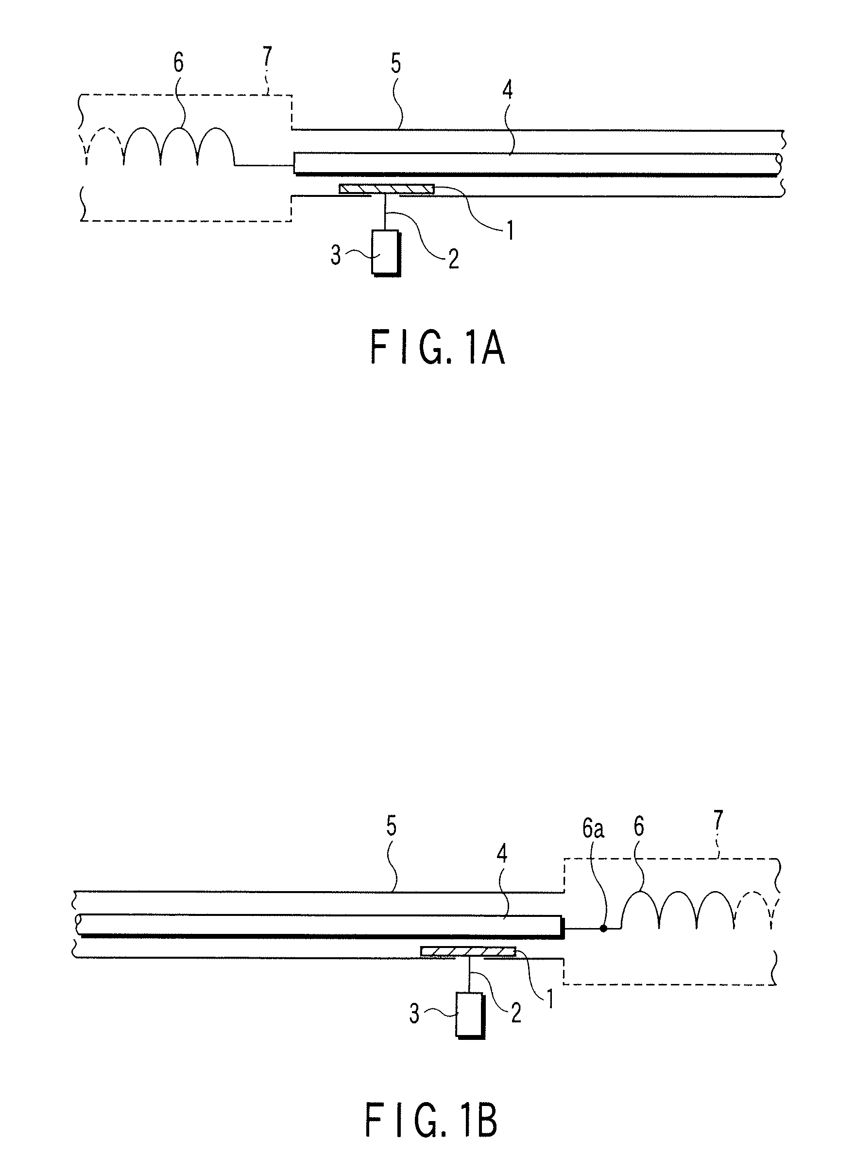
[0080]FIG. 1A is a view showing a partial discharge detection apparatus of an electrical rotating machine according to the present invention, which uses a power line connected to stator windings. FIG. 1B is a view showing a partial discharge detection apparatus of an electrical rotating machine, which uses a neutral point lead line connected to the neutral point of stator windings.

[0081] Referring to FIGS. 1A and 1B, a stator winding 6 corresponding to one phase of the three phases (FIGS. 1A and 1B show one phase) of the electrical rotating machine is stored in a slot formed in a stator core (not shown) attached to the inner surface of a stator frame 7.

[0082] A cylindrical metal frame 5 is attached to the stator frame 7. In FIG. 1A, an insulating support (not shown) supports a power line 4 connected to the stator winding 6. The power line 4 is arranged on the central axis in the metal frame 5. In FIG. 1B, an insulating support (not shown) supports a neutral point lead line 4 connec...

second embodiment

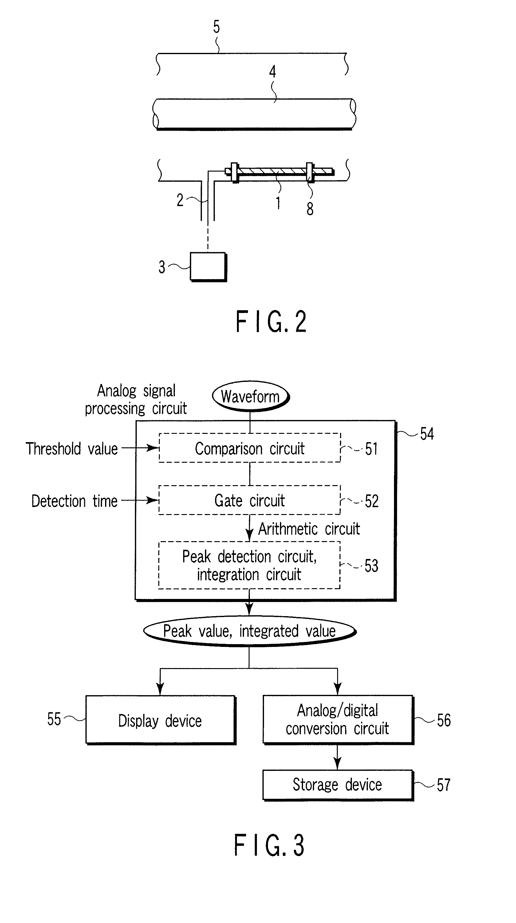
[0095]FIG. 7A is an axial sectional view showing a partial discharge detection apparatus of an electrical rotating machine according to the present invention. FIG. 7B is a radial sectional view. The same reference numbers as in FIGS. 1A, 1B, and 2 denote the same parts in FIGS. 7A and 7B.

[0096] In the second embodiment, as shown in FIGS. 7A and 7B, a plurality of rod antennas 1 serving as a sensor are arranged on the inner surface of a metal frame 5 at equal angular intervals about a power line or neutral point lead line 4. Antenna support insulating members 8 fixed to the metal frame 5 support the rod antennas 1. A connection conductor 10 commonly connects one end of each rod antenna 1. The connection conductor 10 is connected to a detector 3 through a signal lead line 2.

[0097]FIG. 8 shows the relationship between the number of rod antennas and the detection sensitivity=(the first wave peak value of the detection waveform of the sensor) / (the first wave peak value of the waveform p...

third embodiment

[0102]FIG. 10A is an axial sectional view showing a partial discharge detection apparatus of an electrical rotating machine according to the present invention. FIG. 10B is a radial sectional view thereof. The same reference numbers as in FIGS. 1A and 1B denote the same parts in FIGS. 10A and 10B.

[0103] Referring to FIGS. 10A and 10B, a stator winding 6 corresponding to one phase of the three phases (FIGS. 10A and 10B show one phase) of the electrical rotating machine is stored in a slot formed in a stator core (not shown) attached to the inner surface of a stator frame 7.

[0104] A cylindrical metal frame 5 is attached to the stator frame 7. An insulating support (not shown) supports a power line or neutral point lead line 4 connected to the stator winding 6. The power line or neutral point lead line 4 is arranged on the central axis in the metal frame 5. A cylindrical electrode 11 electrostatically coupled to the power line or neutral point lead line 4 is arranged concentrically abo...


PUM


Abstract

A partial discharge detection apparatus of an electrical rotating machine includes a metal frame connected to a stator frame of the electrical rotating machine, a power line connected to one of a stator winding corresponding to one phase of three phases in the metal frame and a neutral point lead line connected to a neutral point of three-phase stator windings and arranged in the metal frame to propagate a partial discharge signal generated by degradation of the stator winding, a sensor including a rod antenna which is installed around the power line or neutral point lead line in the metal frame to electrostatically and magnetically induce the partial discharge signal propagated to the power line or neutral point lead line, and a detector which receives, via a signal lead line, a signal generated in the sensor and detects partial discharge by signal processing.

Description

CROSS-REFERENCE TO RELATED APPLICATIONS [0001] This is a Continuation Application of PCT Application No. PCT / JP2005 / 015159, filed Aug. 19, 2005, which was published under PCT Article 21(2) in Japanese. [0002] This application is based upon and claims the benefit of priority from prior Japanese Patent Applications No. 2004-241217, filed Aug. 20, 2004; and No. 2004-245465, filed Aug. 25, 2004, the entire contents of both of which are incorporated herein by reference. BACKGROUND OF THE INVENTION [0003] 1. Field of the Invention [0004] The present invention relates to a partial discharge detection apparatus and detection method of an electrical rotating machine. [0005] 2. Description of the Related Art [0006] When a high-voltage electrical rotating machine is continuously operated for a long time, degradation of electrical insulation inside the machine progresses due to electrical, thermal, mechanical, and environmental stress. This may finally lead to dielectric breakdown and malfuncti...

Claims


Application Information

Patent Timeline
Patent Type & Authority Applications(United States)
IPC IPC(8): H01H9/50
CPCG01R31/1227G01R31/34G01R31/346
Inventor KANEIWA, HIROSHISAKAI, MASAHIROINOUE, YOSHIYUKISEKITO, SHINOBU
Owner KK TOSHIBA
Why Eureka
Try Eureka