Variable attenuator

a variable attenuator and variable technology, applied in the field of sequential variable attenuators, can solve the problems of large variation in manufacturing, and achieve the effects of small manufacturing variation, easy application to electronic devices, and easy variation of attenuation

Inactive Publication Date: 2007-06-21
PANASONIC CORP
View PDF5 Cites 6 Cited by
  • Summary
  • Abstract
  • Description
  • Claims
  • Application Information

AI Technical Summary

Benefits of technology

[0035] According to the present invention, the variable attenuator which can easily vary the attenuation in many stages can be realized.
[0036] According to the present invention, the variable attenuator which can sequentially vary the attenuation effectively by increasing the number of stages can be realized.
[0037] According to the present invention, the high-precision variable attenuator having the small manufacturing variation can be realized.
[0038] According to the present invention, there can be provided an effect that the variable attenuator which has the relation in which the control voltage and the attenuation GL expressed in logarithm (dB) can be expressed approximately linearly by setting the output impedance and the input impedance of the circuit connected to the input side and the output side of the variable attenuator to the value which satisfies the predetermined matching condition, and which can be easily applied to an electronic device, can be realized.
[0039] According to the present invention, the variable attenuator which has the pair of signal input terminals receiving the balanced signal pair (differential signal pair) or the complementary signal pair and the pair of signal output terminals and can be prevented from being affected by external disturbance can be realized.

Problems solved by technology

Although a variable attenuator using a MOS transistor has been proposed conventionally to implement the above function, it can only implement discrete control or even when sequential variation can be implemented, its variation in manufacturing is large.

Method used


Image

  • Variable attenuator
  • Variable attenuator
  • Variable attenuator

Examples


embodiment 1

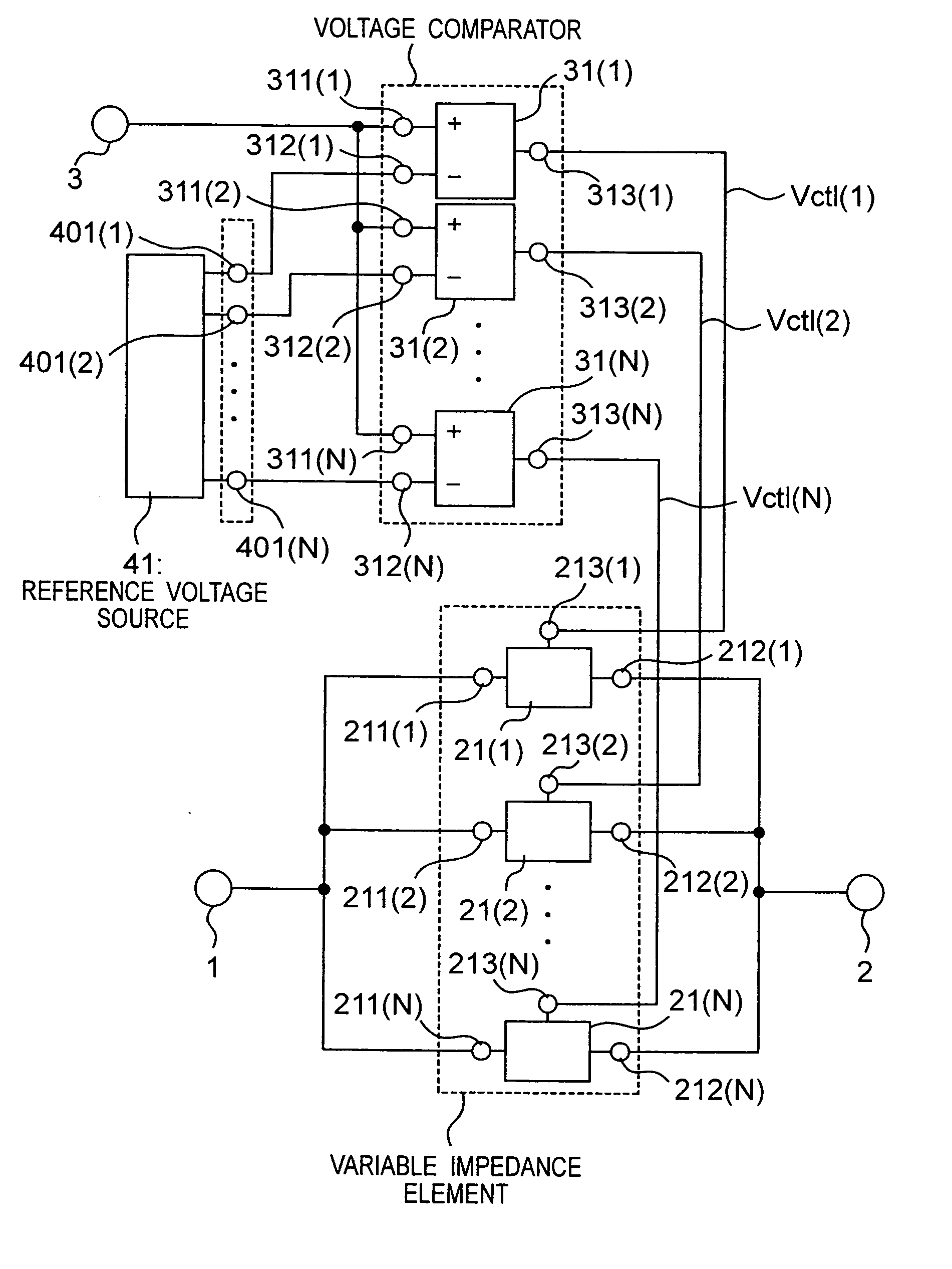
[0075] A variable attenuator according to a first embodiment of the present invention will be described with reference to FIGS. 1 to 7. FIG. 1 is a circuit diagram showing the variable attenuator according to the first embodiment of the present invention.

[0076] The variable attenuator has a signal input terminal 1 receiving a signal of which attenuation is to be controlled, a signal output terminal 2 outputting an attenuated signal, a control terminal 3 receiving a control voltage from the outside, N (positive integer satisfying N≧2) variable impedance elements 21(1) to 21(N), N voltage comparators 31(1) to 31(N), and a reference voltage source 41.

[0077] The N voltage comparators 31(i) (1≦i≦N) have the same circuit configuration and the same circuit constant. The N voltage comparators 31(1) to 31(N) and the reference voltage source 41 constitute an analog / digital converter which converts the control voltage inputted via the control terminal 3, to N control signals Vctl(i) (1≦i≦N)....

embodiment 2

[0119] A variable attenuator according to a second embodiment will be described with reference to FIGS. 8 and 9. FIG. 8 shows the variable attenuator according to the second embodiment of the present invention. In FIG. 8, the same reference numerals indicate the same elements as those shown in FIG. 1.

[0120] The variable attenuator in the second embodiment is different from that in the first embodiment in respect to have a pair of signal input terminals 1 and 4 receiving a signal of which attenuation is controlled, a pair of signal output terminals 2 and 5 outputting an attenuated signal and a variable impedance element 81(i) (1≦i≦N).

[0121] Since the other configuration (the analog / digital converter and the like) is the same as that in the first embodiment, their detailed descriptions will be omitted. The variable impedance element according to the second embodiment will be described.

[0122] The variable impedance elements 81(1) to 81(N) have the same circuit configuration and the ...

embodiment 3

[0131] A variable attenuator according to a third embodiment of the present invention will be described with reference to FIG. 10. The variable attenuator according to the third embodiment has an analog / digital converter which is different from that in the first embodiment. The other configuration of the variable attenuator according to the third embodiment is the same as that in the first embodiment. A configuration of the analog / digital converter of the variable attenuator according to the third embodiment will be described.

[0132]FIG. 10 is a block diagram showing the configuration of the analog / digital converter in the third embodiment. The analog / digital converter in the third embodiment has a configuration shown in FIG. 10 instead of the reference voltage source 41 and the voltage comparator 31 in the first embodiment.

[0133] Referring to FIG. 10, the analog / digital converter is a sequentially comparative type which has an input buffer 1001 connected to a control terminal 3, a...


PUM


Abstract

A variable attenuator which can sequentially control attenuation effectively and has a small variation in manufacturing, is provided. The variable attenuator has a first signal input terminal; a first signal output terminal; a first control terminal receiving a control voltage; an analog/digital converter converting the control voltage to M (M is a positive integer of 2 or more) control signals; and N (N is a positive integer satisfying N≧M) variable impedance elements which are connected in parallel and/or in series between the first signal input terminal and the first signal output terminal, and each impedance of which is varied by either one of the control signals.

Description

TECHNICAL FIELD [0001] The present invention relates to a sequential variable attenuator using a MOS transistor. BACKGROUND ART [0002] Recently, a high-frequency transistor made of a material such as Si or SiGe has been increasingly developed and high integration and high functioning have been implemented. Thus, a power amplifier, a drive amplifier for the power amplifier, a low noise amplifier or the like needs to control sequentially amplification or an incorporate sequential variable attenuator. Although a variable attenuator using a MOS transistor has been proposed conventionally to implement the above function, it can only implement discrete control or even when sequential variation can be implemented, its variation in manufacturing is large. [0003] The conventional variable attenuator using the MOS transistor will be described in detail with reference to FIG. 11. FIG. 11 is a diagram showing the conventional variable attenuator using the MOS transistor. [0004] The conventional...

Claims


Application Information

Patent Timeline
Patent Type & Authority Applications(United States)
IPC IPC(8): H03G3/00H03M1/12H03G1/00H03H11/24H03K19/0175H03M1/38
CPCH03G1/007H03H11/245
Inventor KOJIMA, IWAO
Owner PANASONIC CORP
Why Eureka
Try Eureka