
MEMS Micromirror Surface Plasmon Resonance Biosensor and Method

a micromirror surface and plasmon resonance technology, applied in the field of mems micromirror surface plasmon resonance biosensor and method, can solve the problems of limiting the detection sensitivity and signal variation across the spo

Inactive Publication Date: 2007-06-21
PLEXERA LLC +1
View PDF17 Cites 17 Cited by
  • Summary
  • Abstract
  • Description
  • Claims
  • Application Information

AI Technical Summary

Problems solved by technology

However, expanding a spot Gaussian profile from a laser source using optical elements does not necessarily provide homogeneous illumination, which results in signal variation across the spot, i.e., sensing area.
This requires a background correction that can limit the sensitivity of detection.
This is particularly challenging for imaging larger areas by SPR, especially when within the larger areas there is a need for uniform detection, such as in a microarray.

Method used


Image

  • MEMS Micromirror Surface Plasmon Resonance Biosensor and Method
  • MEMS Micromirror Surface Plasmon Resonance Biosensor and Method
  • MEMS Micromirror Surface Plasmon Resonance Biosensor and Method

Examples


examples

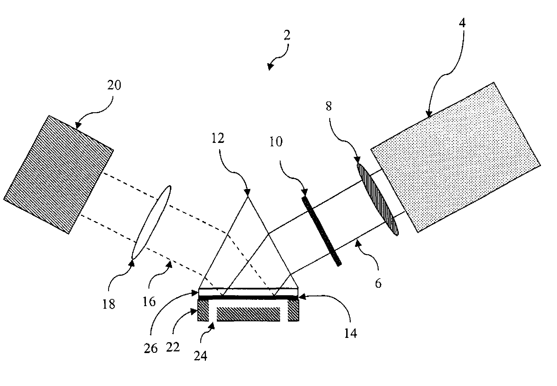
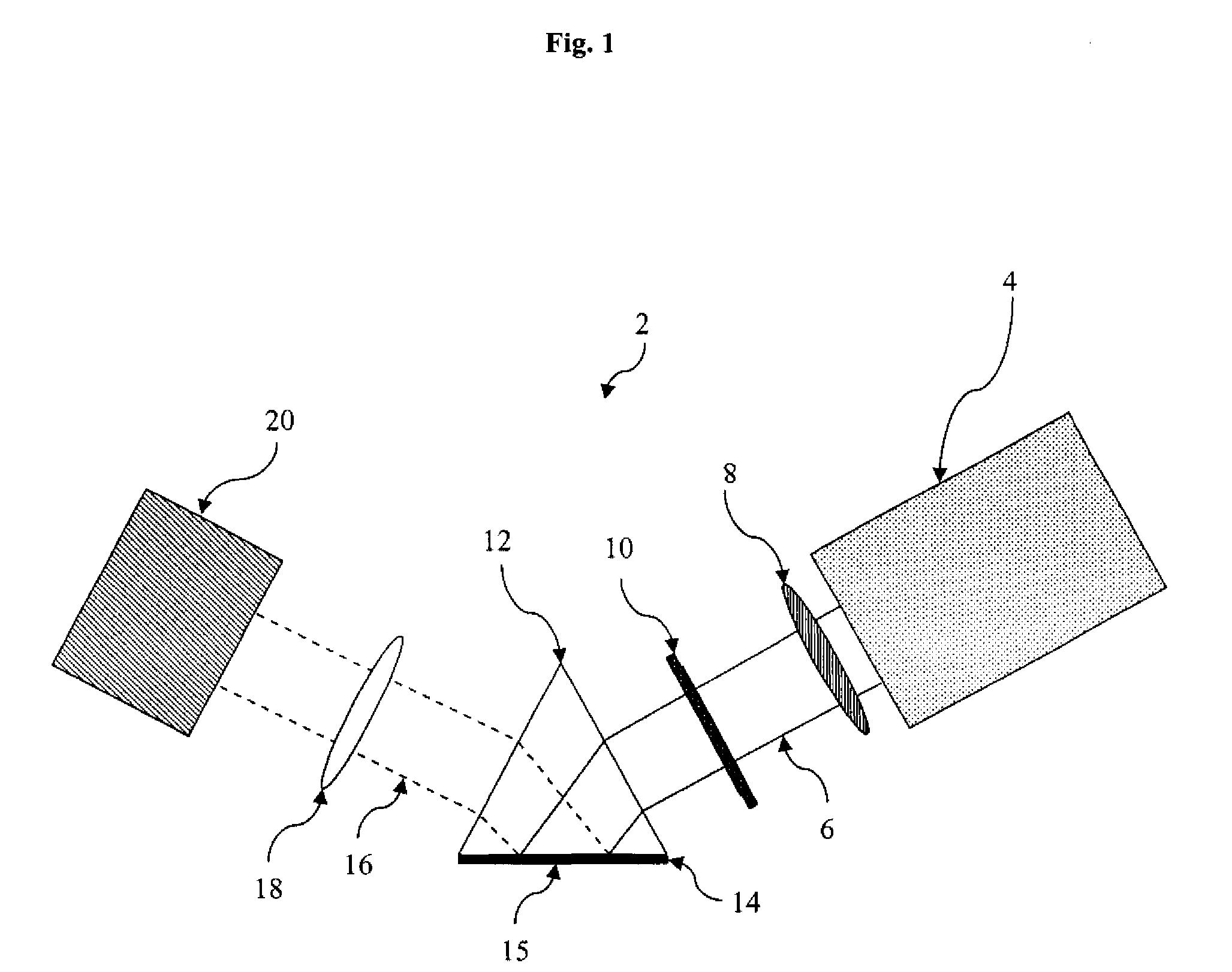
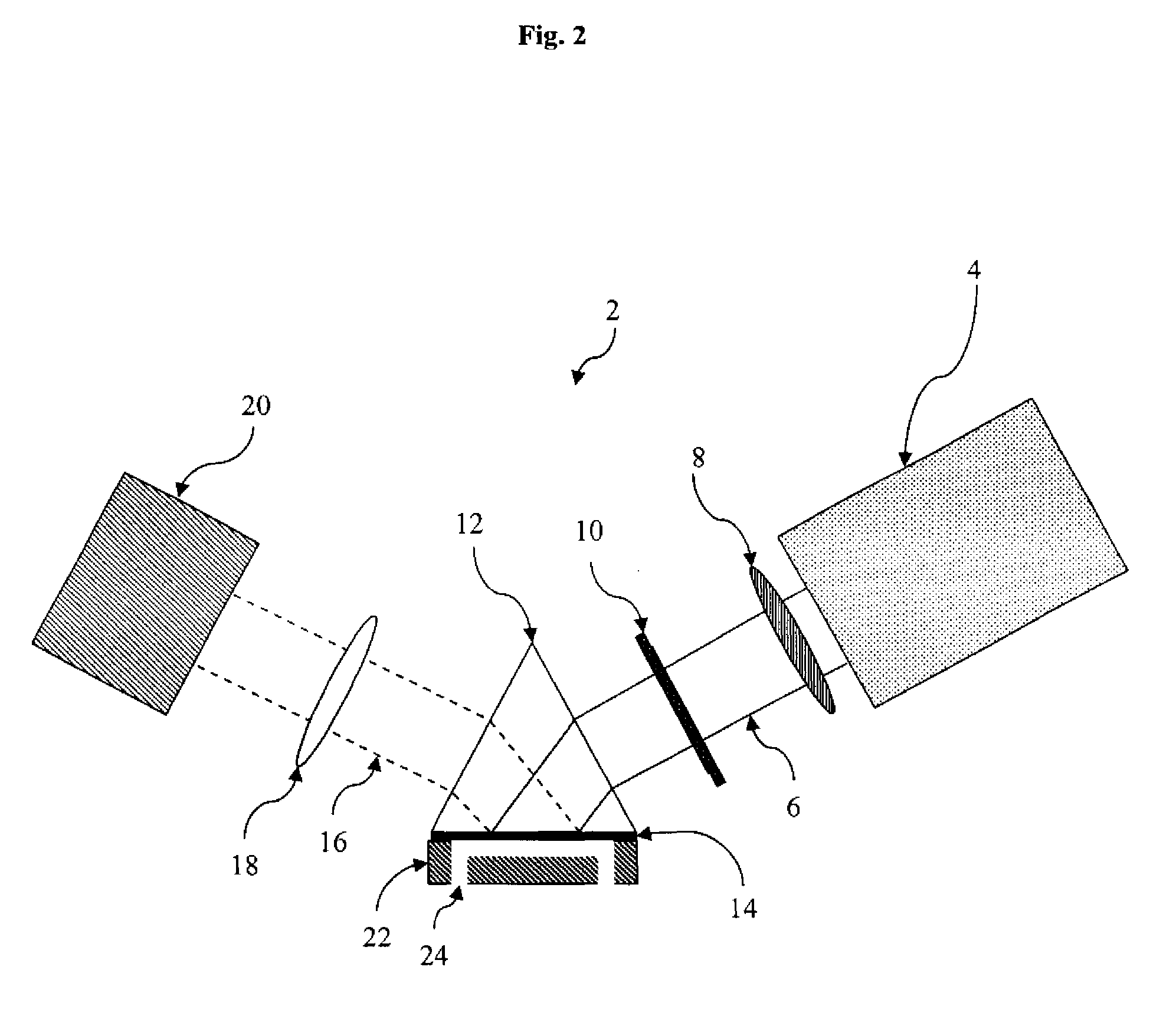
[0018] A surface plasmon resonance (SPR) sensing instrument using a Kretschmann configuration was constructed using a micromirror scanner device available from Microvision, Inc of Bothell, Wash. and described in U.S. Pat. No. 6,245,590; U.S. Pat. No. 6,362,912; U.S. Pat. No. 6,433,907; and U.S. Pat. No. 5,629,790. The micromirror scanner device is that used in the NOMAD product. The light source was a laser beam pigtailed in from the micromirror scanner device controller box unit had a wavelength of 658 nm. The laser beam carried a maximum power of 35 mW. The Krestschmann configuration prism coupler module included a prism made from high index material (Shott SF10 glass), a replaceable substrate, and a flow cell that carried solution under study. The substrate was made from the same material as the prism and was coupled with the prism through an index liquid matching fluid (Cargille labs, 1815Y) from the non-metallic coating side. The thin metal film on the substrate was gold with a...


PUM


Abstract

A method of generating surface plasmon resonance using excitation light directed at a thin metal film by a micromirror is described. A method that uses excitation light directed at a thin metal film by a micromirror scanner device is also described. A surface plasmon resonance imager is described comprising a micromirror that directs light to the surface of a thin metal film. Another method is described, comprising: a) directing light toward a thin metal film using a micromirror and b) detecting dynamic chemical events at or near the surface of the thin metal film. The dynamic events may be, for example, a fluidic change or a binding event.

Description

RELATED APPLICATIONS [0001] This application claims the benefit of priority under 35 U.S.C. §119(e)(1) to U.S. provisional application 60 / 687,964, filed Jun. 7, 2005.BACKGROUND [0002] All patents, patent applications, and publications cited within this application are incorporated herein by reference to the same extent as if each individual patent, patent application, or publication was specifically and individually incorporated by reference. [0003] The invention relates to detecting molecular binding events as well as photochemical spectral emission and / or absorption in a two-dimensionally discriminated manner such as, for example, in an array. The observation of molecular binding and affinity is a key element in biochemical and pharmaceutical research and development and analytical assays. In this field, the use of arrays is desirable in order to increase assay throughput and decrease the amount of expensive reagents consumed. Microarray technologies are commonly used in fluoresce...

Claims


Application Information

Patent Timeline
IPC IPC(8): G01N21/55
CPCB82Y15/00B82Y30/00G01N21/05G01N21/253G01N21/553G01N21/6452G01N21/648
Inventor GUAN, HANN WENCONG, SHUXINLIANG, MINHUAJOHNSON, ERIC
Owner PLEXERA LLC
Learn More