

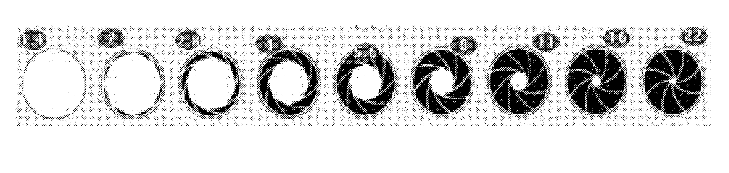
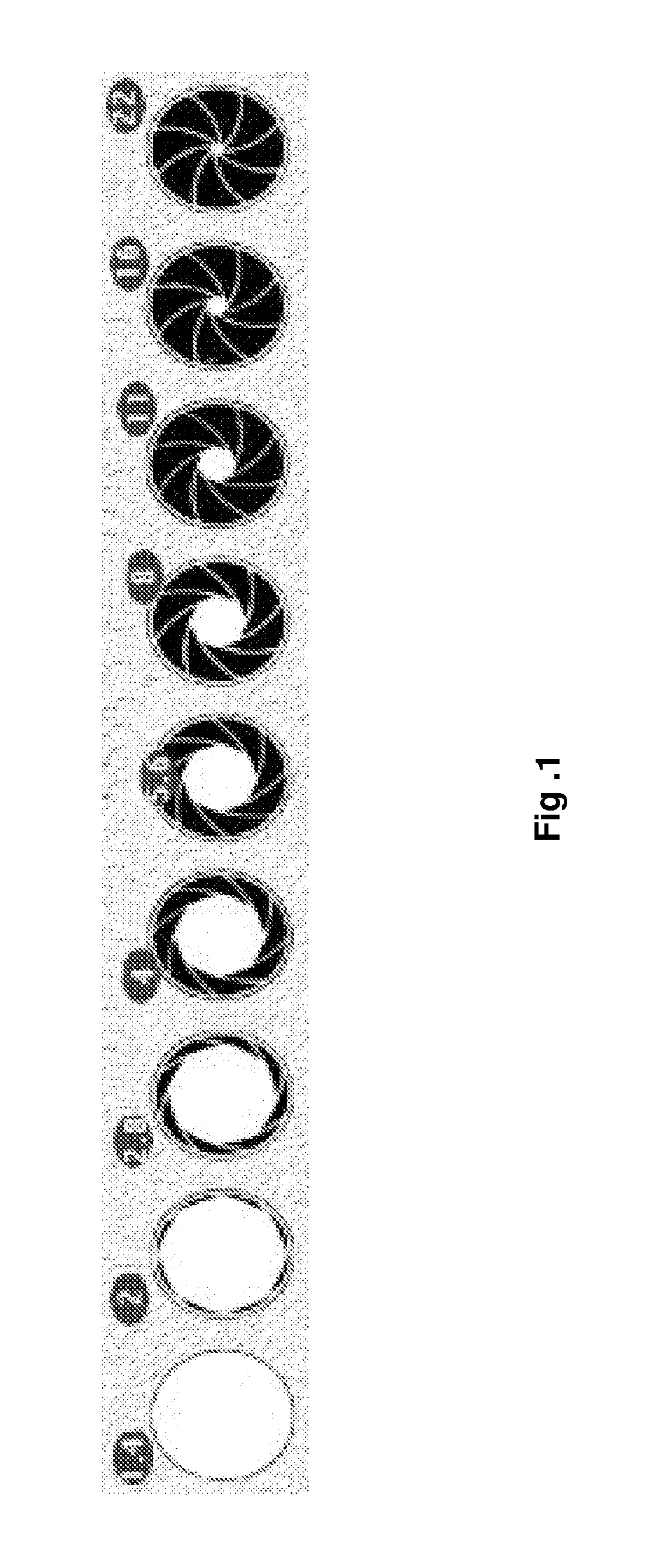
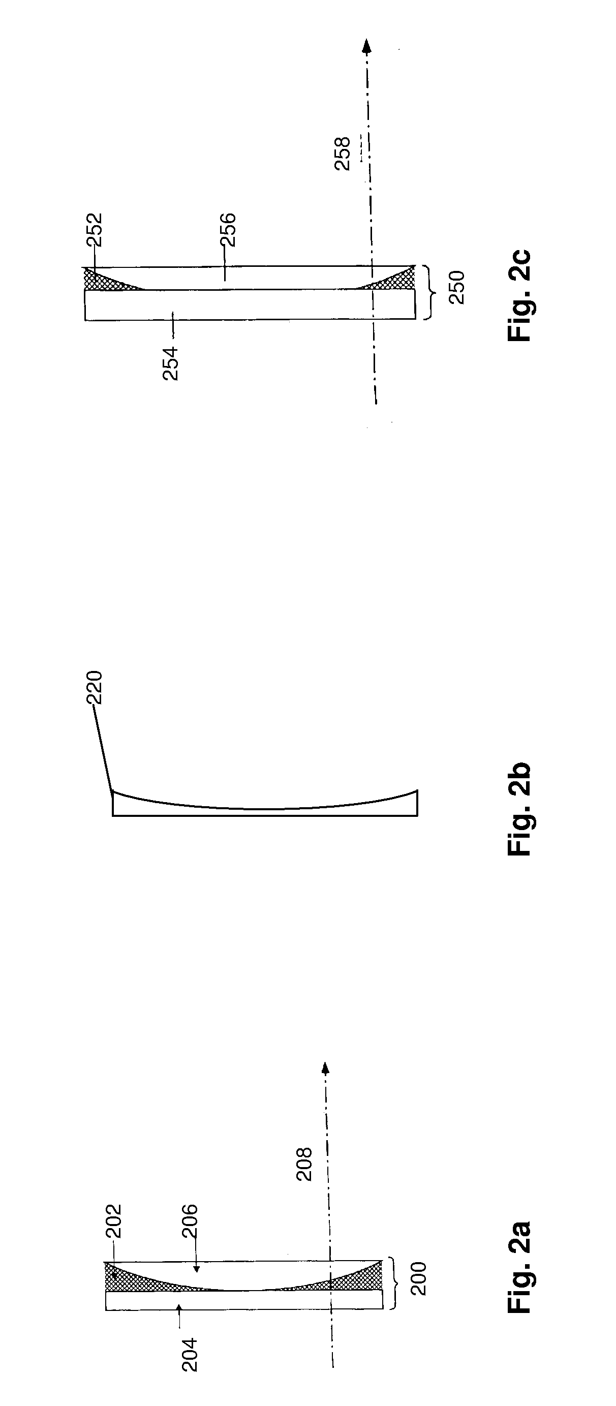
Adjustable apodized lens aperture
a technology of aperture adjustment and lens, applied in the field of optical systems, can solve the problems of inconvenient use, prohibitively expensive for a $4.50 camera module intended for computer or cellular telephone applications, and neither produced good quality images at low-light level, and achieve the effect of facilitating transmission of uv energy
- Summary
- Abstract
- Description
- Claims
- Application Information
AI Technical Summary
Benefits of technology
Problems solved by technology
Method used
Image

Examples
Embodiment Construction
[0027] Reference will now be made in detail to specific embodiments of the invention including the best modes contemplated by the inventor for carrying out the invention. Examples of these specific embodiments are illustrated in the accompanying drawings. While the invention is described in conjunction with these specific embodiments, it will be understood that it is not intended to limit the invention to the described embodiments. On the contrary, it is intended to cover alternatives, modifications, and equivalents as may be included within the spirit and scope of the invention as defined by the appended claims. In the following description, specific details are set forth in order to provide a thorough understanding of the present invention. The present invention may be practiced without some or all of these specific details. In addition, well known features may not have been described in detail to avoid unnecessarily obscuring the invention.
[0028] According to various embodiments...
PUM
 Abstract
Description
Claims
Application Information