System and Method for Hydrothermal Reactions - Two Layer Liner

a hydrothermal reaction and two-layer technology, applied in the direction of superimposed coating process, supercritical condition process, transportation and packaging, etc., can solve the problems of inability to achieve oxidation degree, inability to use conventional wet oxidation, inability to reduce reaction times of this length, etc., to achieve the effect of preventing accumulation of insoluble salts on the liner and reducing corrosion rates

Inactive Publication Date: 2007-06-21
GENERAL ATOMICS
View PDF1 Cites 12 Cited by
  • Summary
  • Abstract
  • Description
  • Claims
  • Application Information

AI Technical Summary

Benefits of technology

[0017] For the present invention, partitions can be positioned within the porous layer, with each partition extending from the corrosion resistant layer to the pressure bearing wall. Thus, the partitions divide the porous layer into sections and isolate the sections from each other. If partitions are used, separate connectors can be provided for each section to thereby allow each section to be independently heated, cooled and monitored for leaks. Also, an optional layer of insulation can be selectively interposed between the porous layer of the liner and the wall of the reactor vessel to insulate the pressure bearing wall of the reactor vessel.
[0018] In operation, a warming fluid can be selectively passed through the porous layer to pre-heat the reactor chamber during periods preceding steady state treatment conditions. Additionally, a coolant can be selectively passed through the porous layer of the liner during the hydrothermal treatment of the reactants to cool the pressure bearing wall and the corrosion resistant layer of the liner. By maintaining the temperature of the corrosion resistant layer of the liner at sub-critical temperatures, corrosion rates can be reduced and the accumulation of insoluble salts on the liner can be prevented. Also in accordance with the present invention, the connectors can be utilized to perform leak detection measurements during the hydrothermal treatment of the reactants to ensure the continuous integrity of the corrosion resistant layer of the liner.

Problems solved by technology

In many applications, reaction times of this length are unacceptable.
In addition to unacceptably long reaction times, the utility of conventional wet oxidation is limited by several factors.
These include: the degree of oxidation attainable; an inability to adequately oxidize refractory compounds; and the lack of usefulness for power recovery due to the low temperature of the process.
Due to the corrosive effect of HCl, it may be necessary to intentionally add alkali to the reactor to avoid high concentrations of hydrochloric acid in the reactor.
Also, hydrogen bonding, a short-range phenomenon, is almost entirely disrupted, and the water molecules lose the ordering that is responsible for many of the characteristic properties of water at STP.
Further, at typical SCWO conditions, smaller polar and nonpolar organic compounds, having relatively high volatility, will exist as vapors and are completely miscible with supercritical water.
The lack of solubility of salts in supercritical water causes the salts to precipitate as solids and deposit on process surfaces causing fouling of heat transfer surfaces and blockage of the process flow.
A key issue pertaining to hydrothermal treatment processes is the means by which feed streams containing or generating sticky solids are handled.
It is well-known that such feed streams can result in the accumulation of solids that will eventually plug the process equipment.
Unfortunately, the liner disclosed by Dassel et al. fails to adequately address the problem associated with insoluble salt buildup and reactor plugging.
Hervert et al., however, does not disclose the use of the liner for hydrothermal treatment environments, and consequently, the disclosed liner lacks at least one very important feature necessary for using a liner in hydrothermal treatment, namely, a suitable mechanism for relieving the effects of insoluble salt buildup and reactor plugging.

Method used


Image

  • System and Method for Hydrothermal Reactions - Two Layer Liner
  • System and Method for Hydrothermal Reactions - Two Layer Liner
  • System and Method for Hydrothermal Reactions - Two Layer Liner

Examples


Embodiment Construction

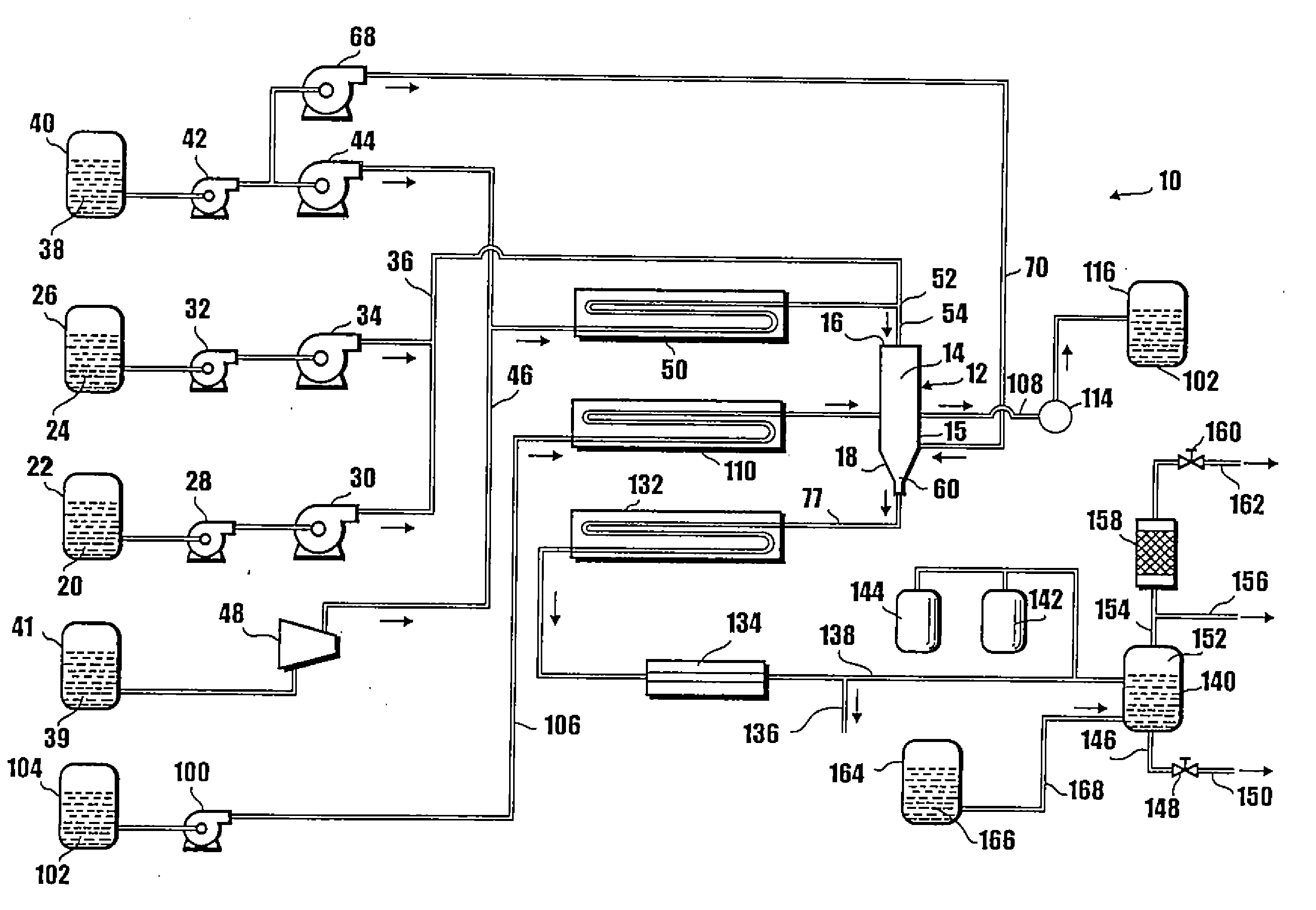
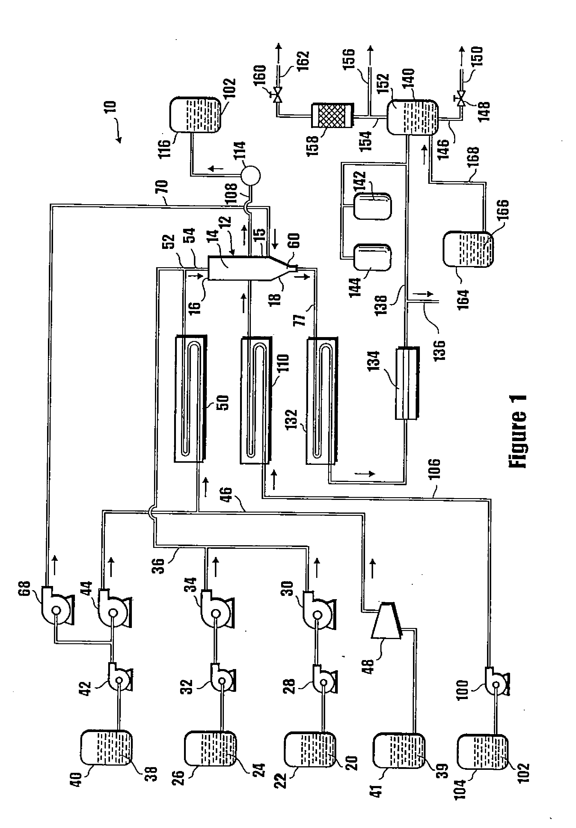
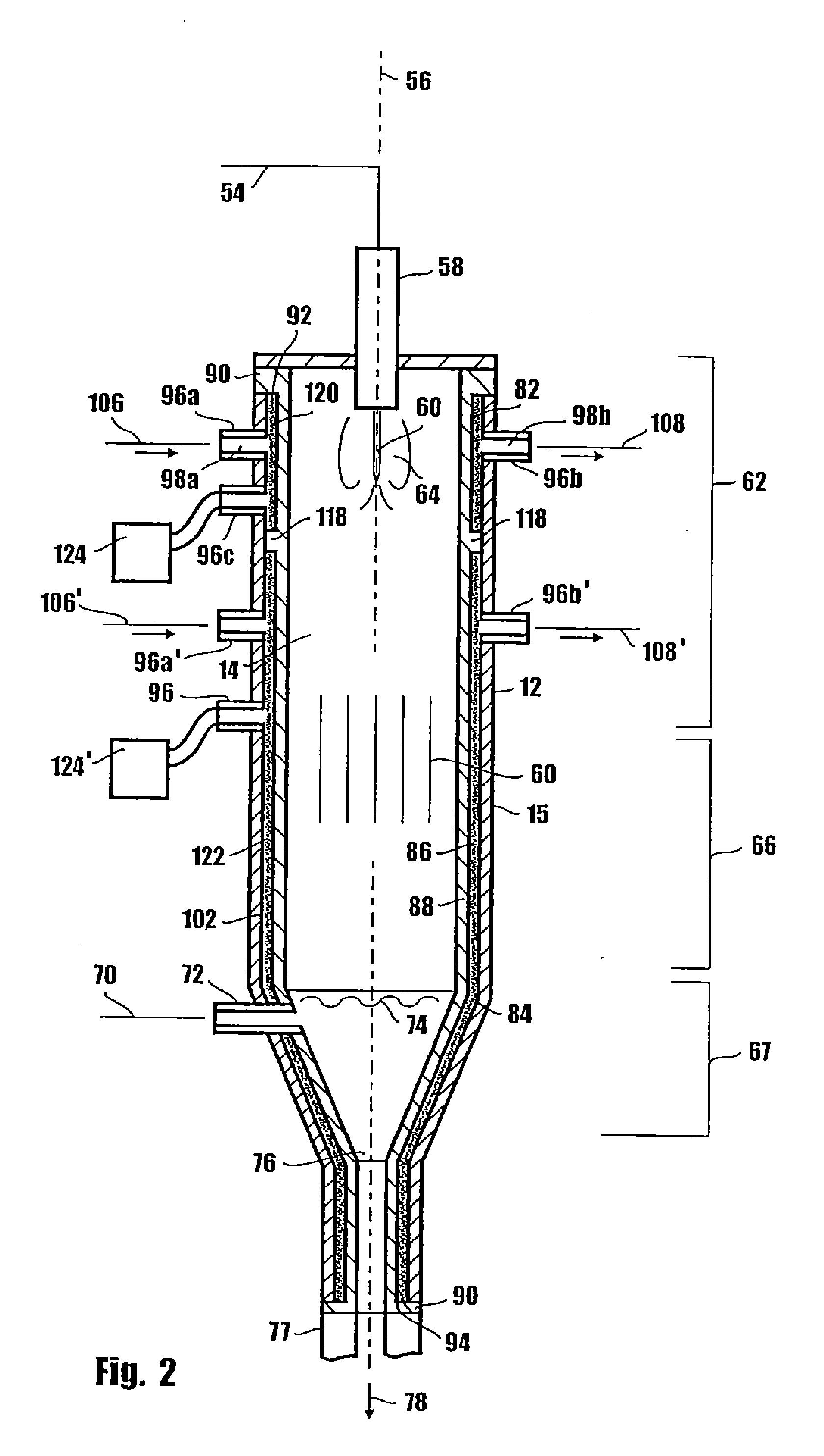
[0013] In accordance with the present invention, a system for performing hydrothermal treatment at temperatures above three hundred seventy-four degrees Celsius (374° C.) and pressures above about 25 bars, includes a reactor vessel that is formed with a pressure bearing wall which surrounds a reactor chamber. Generally, the feed material is introduced into the reactor chamber from one end of the reactor vessel and the reaction products are withdrawn from the other end of the reactor vessel.

[0014] The surface of the pressure bearing wall that faces the reactor chamber is covered by a liner to protect the wall from exposure to temperature extremes, corrosives and salt deposits. The liner is formed with a porous layer and a non-porous, corrosion resistant layer. The corrosion resistant layer is positioned adjacent to the porous layer to interpose the porous layer between the corrosion resistant layer and the wall of the vessel. Seals extend from the ends of the corrosion resistant lay...


PUM

PropertyMeasurementUnit
pressureaaaaaaaaaa
temperatureaaaaaaaaaa
pressureaaaaaaaaaa

Abstract

A system and method for performing hydrothermal treatment includes a reactor vessel having a pressure bearing wall. The surface of the pressure bearing wall that faces the reactor chamber is covered by a liner to protect the wall from exposure to temperature extremes, corrosives and salt deposits. The liner is formed with a porous layer and a non-porous, corrosion resistant layer. The corrosion resistant layer is positioned adjacent to the porous layer to seal the porous layer between the corrosion resistant layer and the wall of the vessel. Connectors extend through the wall of the reactor vessel to allow for fluid communication between the porous layer and an externally located pump. A heat transfer fluid can be selectively passed through the porous layer to maintain the temperature of the liner.

Description

[0001] This application is a divisional of application Ser. No. 09 / 753,319, filed Dec. 28, 2000, which is currently pending. The contents of application Ser. No. 09 / 753,319 are incorporated herein by reference.FIELD OF THE INVENTION [0002] The present invention pertains generally to methods and systems for hydrothermal treatment to destruct waste, recovery heat, or produce beneficial chemicals. More specifically, the present invention pertains to methods and systems for the hydrothermal treatment of organics which contain inorganic compounds such as salts or oxides or which will generate these inorganic compounds. The present invention is particularly, but not exclusively, useful as a method and system for the hydrothermal treatment of organics under supercritical temperature and pressure conditions, or at supercritical temperatures and elevated, yet subcritical pressures. BACKGROUND OF THE INVENTION [0003] The process of wet oxidation has been used for the treatment of aqueous stre...

Claims


Application Information

Patent Timeline
Patent Type & Authority Applications(United States)
IPC IPC(8): B01J19/00C23C28/00
CPCC23C28/023C23C28/028B01J3/008B01J3/02B01J3/048B01J2219/00094Y10T428/249953
Inventor HAZLEBECK, DAVID A.
Owner GENERAL ATOMICS
Why Eureka
Try Eureka