Method and apparatus for strengthening a porous substrate

a technology of porous substrates and strengthening methods, applied in the direction of chemistry apparatus and processes, coatings, layered products, etc., can solve the problems of not being able to identify the open pore network substrates, not being able to achieve particularly accurate characterization, and limited permeability, so as to achieve the effect of increasing the strength of the substrate, high porosity and high strength characteristics

Inactive Publication Date: 2007-06-21
GE02 TECH INC
View PDF98 Cites 19 Cited by
  • Summary
  • Abstract
  • Description
  • Claims
  • Application Information

AI Technical Summary

Benefits of technology

[0011] Briefly, the present invention provides a process for strengthening a porous substrate. The process includes providing a substrate having intersecting fibers, where the intersecting fibers cooperate in the final substrate product to form an open pore network. Pathways are opened into the fibrous substrate structure, which enable a flow of gas into the or through the substrate. The substrate is positioned in a CVD (chemical vapor deposition) station, and one or more layers of a strengthening agent is deposited. The deposited layer or layers form a strong coating around fibers and fiber intersections to provide additional strength to the substrate. The strengthened substrate may then be used in wide variety of applications and fields. Advantageously, the disclosed fiber strengthening process produces a substrate having high porosity and higher strength characteristics as compared to a non-strengthened substrate.

Problems solved by technology

However, this is not a particularly accurate characterization, as a substrate may be quite porous but still have limited permeability if the pores are not generally open and interconnected.
In this way, there are many voids and open spaces within the foam, but since the pore are not connected, the fluid or gas cannot flow from one side of the foam to the other.
However, such open pore network substrates are not known in the filtering or catalytic industries.
However, because a higher porosity substrate has less structural material, it may need additional strength to operate in some environments.
However, extrusion of powdered ceramic material has reached a practical upper limit of porosity, and further increases in porosity appear to result in an unacceptably low strength.
For example, as porosity is increased beyond 60%, the extruded ceramic powder substrate has not proven strong enough to operate in the harsh environment of a diesel particulate filter.
In order to increase surface area, extruded ceramic powder substrates have tried to increase cell density, but the increase in cell density has resulted in an unacceptable back pressure to the engine.
Thus, the extruded ceramic powder substrate does not have sufficient strength at very high porosities, and also produces unacceptable back pressure when there is a need for increased surface area.
Accordingly, the extrusion of ceramic powder appears to have reached its practical utility limits.
However, the use of the pleated ceramic paper filters has been sporadic, and has not been widely adopted.
For example, pleated ceramic papers have not effectively been used in harsh environments.
Manufacturing the pleated ceramic papers requires the use of a paper making process that creates ceramic paper structures that are relatively weak, and do not appear to be cost-effective as compared to extruded filters.
Further, the formation of pleated ceramic papers allows very little flexibility in cell shape and density.
For example, it is difficult to create a paper pleated filter with large inlet channels and smaller outlet channels, which may be desirable in some filtering applications.
Accordingly, the use of pleated ceramic papers has not satisfied the requirement for higher porosity filter and catalytic substrates.
However, growing these crystals in-situ requires careful and accurate control of the curing process, making the process difficult to scale, relatively expensive, and prone to defects.
Further, this difficult process only gives a few more percentage points in porosity.
Finally, the process only grows a mullite type crystalline whisker, which limits the applicability of the substrate.
For example, mullite is known to have a large coefficient of thermal expansion, which makes crystalline mullite whiskers undesirable in many applications needing a wide operational temperature band.

Method used


Image

  • Method and apparatus for strengthening a porous substrate
  • Method and apparatus for strengthening a porous substrate
  • Method and apparatus for strengthening a porous substrate

Examples


Embodiment Construction

[0022] Detailed descriptions of examples of the invention are provided herein. It is to be understood, however, that the present invention may be exemplified in various forms. Therefore, the specific details disclosed herein are not to be interpreted as limiting, but rather as a representative basis for teaching one skilled in the art how to employ the present invention in virtually any detailed system, structure, or manner.

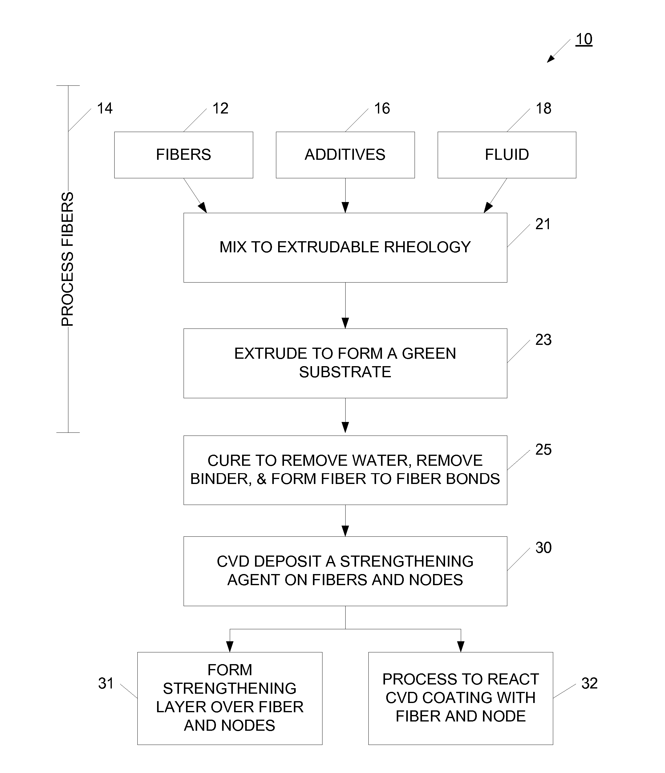
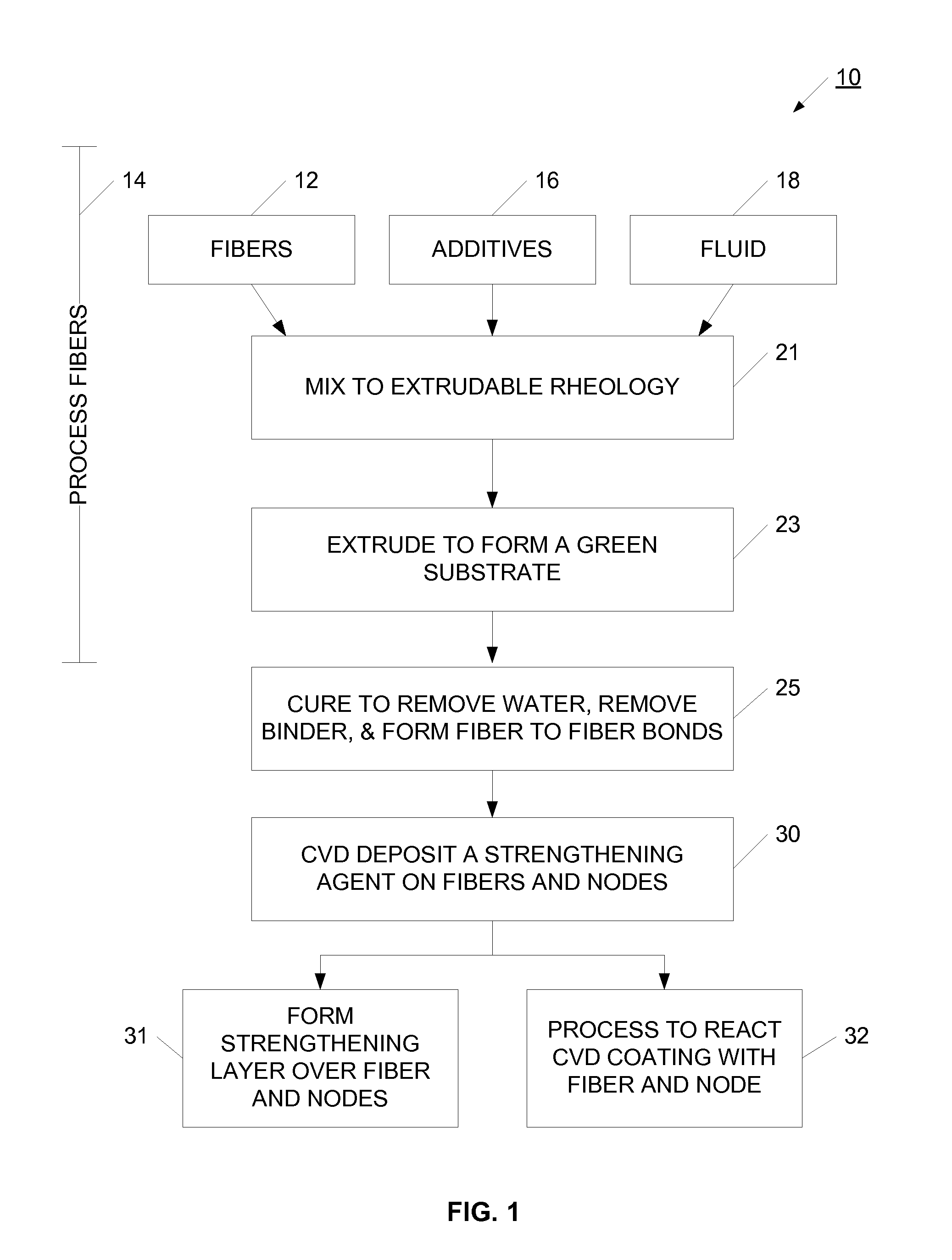
[0023] Referring now to FIG. 1, a process 10 for strengthening a porous substrate is illustrated. In the example illustrated in FIG. 1, the substrate is manufactured using an extrusion process, and then the extruded substrate is strengthened using a CVD (chemical vapor deposition process). Although process 10 uses an extrusion process to provide the substrate, it will be appreciated that other manufacturing processes may be used. For example, the substrate may be provided using a casting, broaching, or other process. As illustrated, process 10 uses an extrusion ...


PUM

PropertyMeasurementUnit
porosityaaaaaaaaaa
porositiesaaaaaaaaaa
porosityaaaaaaaaaa

Abstract

A process is provided for strengthening a porous substrate. The process includes providing a substrate having intersecting fibers, where the intersecting fibers cooperate in the final substrate product to form an open pore network. Pathways are opened into the fibrous substrate structure, which enable a flow of gas into the or through the substrate. The substrate is positioned in a CVD (chemical vapor deposition) station, and one or more layers of a strengthening agent is deposited. The deposited layer or layers form a strong coating around fibers and fiber intersections to provide additional strength to the substrate. The strengthened substrate may then be used in wide variety of applications and fields. Advantageously, the disclosed fiber strengthening process produces a substrate having high porosity and higher strength characteristics as compared to a non-strengthened substrate.

Description

CROSS-REFERENCE TO RELATED APPLICATIONS [0001] This application claims the benefit of U.S. Provisional Patent Application Ser. No. 60 / 753,094, filed on Dec. 21, 2005, the entirety of which is incorporated by reference.BACKGROUND OF THE INVENTION [0002] The present invention relates generally to processes for strengthening a porous substrate, and in one particular implementation to a process for CVD deposition of a strengthening agent into a porous ceramic substrate. [0003] Many applications require strong materials for facilitating and supporting various processes. For example, substrates are used in filtering applications to filter particulate matter, separate different substances, or remove bacteria or germs from air. These substrates may be constructed to operate in air, exhaust gases or liquids, and may be manufactured to endure substantial environmental or chemical stresses. In another example, catalytic materials are deposited on the substrate for facilitating chemical reactio...

Claims


Application Information

Patent Timeline
Patent Type & Authority Applications(United States)
IPC IPC(8): C23C16/00B32B37/00
CPCC23C16/045
Inventor ZUBERI, BILAL
Owner GE02 TECH INC
Why Eureka
Try Eureka