
Ag ALLOY REFLECTIVE FILM FOR OPTICAL INFORMATION RECORDING MEDIUM, OPTICAL INFORMATION RECORDING MEDIUM AND Ag ALLOY SPUTTERING TARGET FOR FORMING Ag ALLOY REFLECTIVE FILM FOR OPTICAL INFORMATION RECORDING MEDIUM

a technology of optical information and reflective film, which is applied in the field of optical information recording medium and ag alloy sputtering target for forming ag alloy reflective film for optical information recording medium, can solve the problems of difficult to provide an id number for individual disks, thermal damage of polycarbonate substrate that is a base and an adhesive, and reduce the reflectance. , to achieve the effect of convenient application

Inactive Publication Date: 2007-06-21
KOBE STEEL LTD +1
View PDF5 Cites 19 Cited by
  • Summary
  • Abstract
  • Description
  • Claims
  • Application Information

AI Technical Summary

Benefits of technology

The invention is about a special reflective film for an optical information recording medium that can be easily applied with laser marking. The film is made up of a combination of specific elements, including silver (Ag), neodymium (Nd), gadolinium (Gd), yttrium (Y), and smithium (Sm). The film has good mark shape and resistance to corrosion. The invention also includes a sputtering target for forming the reflective film. The use of this special reflective film makes it easier to create optical information recording media with laser marking.

Problems solved by technology

Accordingly, it has been difficult to provide an ID number for individual disks.
Accordingly, when these materials are used in the play-only optical disks that are marked with laser, a higher laser power is necessary to mark, and therefore, there are problems in that the polycarbonate substrate that is a base and an adhesive are thermally damaged.
Furthermore, when Ag alloy is used, since Ag is low in the heat resistance, there is a problem in that Ag film agglutinates at high temperatures to thereby lower the reflectance.
However, an Ag alloy thin film satisfying the demand from a viewpoint of a mark shape during laser marking has not been obtained.

Method used


Image

  • Ag ALLOY REFLECTIVE FILM FOR OPTICAL INFORMATION RECORDING MEDIUM, OPTICAL INFORMATION RECORDING MEDIUM AND Ag ALLOY SPUTTERING TARGET FOR FORMING Ag ALLOY REFLECTIVE FILM FOR OPTICAL INFORMATION RECORDING MEDIUM
  • Ag ALLOY REFLECTIVE FILM FOR OPTICAL INFORMATION RECORDING MEDIUM, OPTICAL INFORMATION RECORDING MEDIUM AND Ag ALLOY SPUTTERING TARGET FOR FORMING Ag ALLOY REFLECTIVE FILM FOR OPTICAL INFORMATION RECORDING MEDIUM

Examples


example 1

[0060] In example 1, Ag—Nd—(Ti, Ta, W, Mo, V, Zr, Nb or Cr) thin films were prepared as Ag alloy thin film and evaluated in terms of the reflectance, durability and mark shape. Results are shown in Table 1.

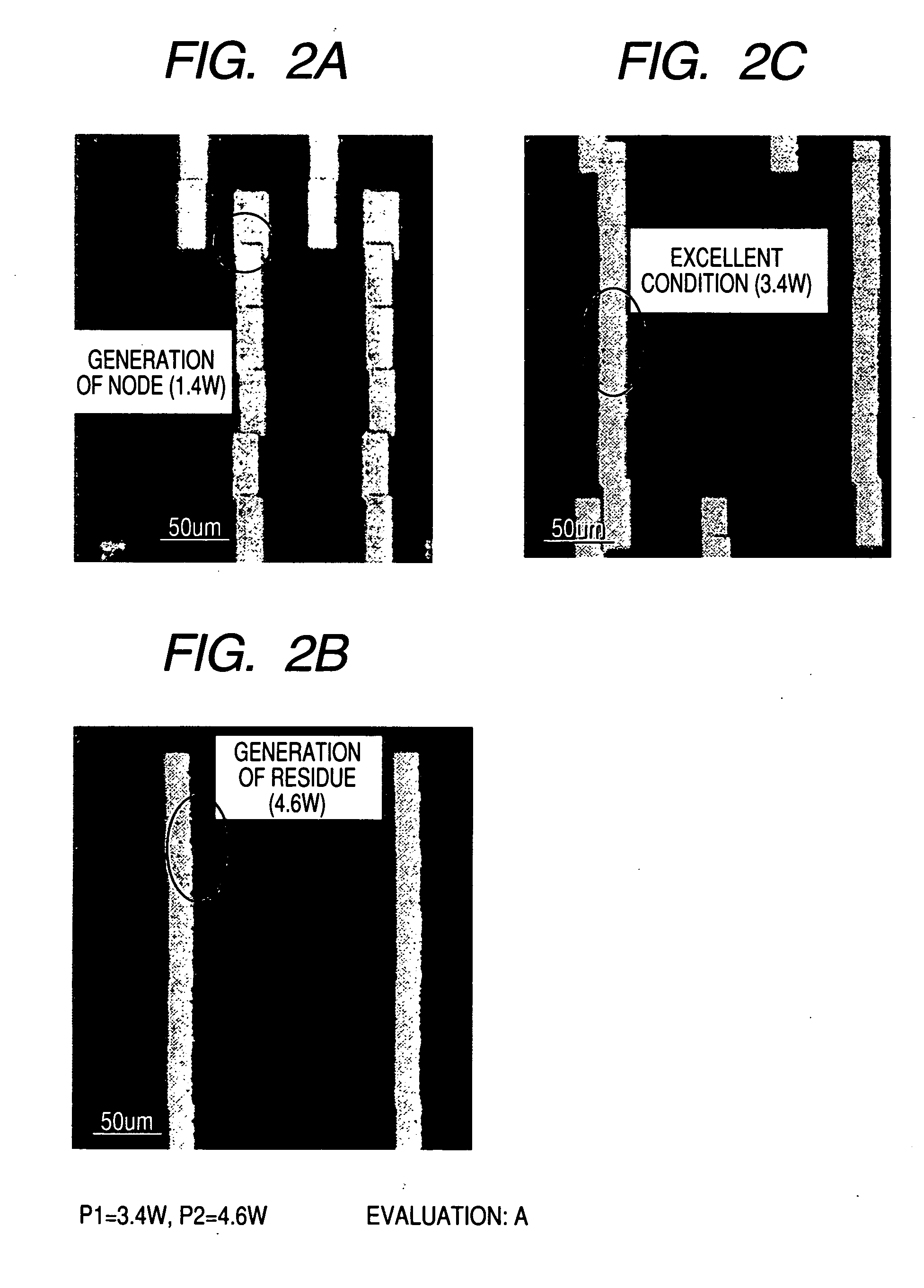
[0061] It is found that in Ag—Nd—(Ti, Ta or W) thin films, as the amount of Ti, Ta or W increases, a power (P1) where the node disappears becomes lower and thereby a recording margin is expanded. Furthermore, a power (P2) where a size of the residue exceeds the upper limit size does hardly depend on the amount of Ti, Ta or W added, and, when a definite amount of the elements is contained, the mark shape can be improved. On the other hand, the reflectance becomes lower in all additive elements as an addition amount thereof is increased. Accordingly, it is found that the amount of an additive element is desirably suppressed in order to maintain the reflectance.

[0062] Test results of Ag alloy thin films shown in Table 1 will be detailed below. Ag alloy thin films of Nos. 1A through...

example 2

[0066] In example 2, Ag—(Nd, Gd, Y or Sm)—(Ti or Ta) thin films were prepared and evaluated of the reflectance, durability and mark shape. Results are shown in Table 2.

[0067] According to the Ag—(Nd, Gd, Y or Sm)—(Ti or Ta) thin films, it is found that as an amount of Nd increases, a power (P2) where a size of the residue exceeds the upper limit dramatically increases to improve the recording margin. This is considered to be corresponding that an addition of Nd or Gd inhibits the agglutination from occurring. On the other hand, as for the durability, it is found that when an amount of Nd exceeds 3.0 atomic percent the durability is remarkably deteriorated. Accordingly, an amount of Nd is necessarily limited to 3.0 atomic percent or less.

[0068] Test results of Ag alloy thin films shown in Table 2 will be detailed below. Ag alloy thin films of Nos. 1B through 6B are Ag—Nd—Ti thin films. Among these, with regard to an Ag—Nd—Ti thin film of No. 1B, since an amount of Nd is 0.1 atomic ...

example 3

[0070] In example 3, Ag—Nd—(Ti, Ta or W)—(Sn or In) thin films were prepared and evaluated of the reflectance, durability and mark shape. Results are shown in Table 3.

[0071] According to the Ag—Nd—(Ti, Ta or W)—(Sn or In) thin films, it is found that when an amount of Sn or In is increased, a power (P1) where a node disappears can be reduced and thereby a margin of the recording power can be effectively expanded. On the other hand, as an addition amount of Sn or In increases, a power (p2) where a size of the residue exceeds an upper limit size decreases. This is considered to be corresponding that since an Ag—Sn alloy is a eutectic alloy, a melting temperature is lowered to lower the viscosity and thereby agglutination tends to occur when the eutectic alloy is added. When Sn or In is added by 7.0 atomic percent, a power (P1) where the node disappears is such small as less than 1.0 W. It is found out that an addition amount of Sn or In is desirably 5.0 atomic percent or less and mor...


PUM

PropertyMeasurementUnit
thicknessaaaaaaaaaa
wavelengthaaaaaaaaaa

Abstract

The invention relates to an Ag alloy reflective film for an optical information recording medium, including Ag as a main component, at least one kind of Nd, Gd, Y and Sm in a total amount of more than 0.1 atomic percent and not more than 3.0 atomic percent and at least one kind of W, Mo, V, Zr, Nb and Cr in a total amount of 3.0 to 10.0 atomic percent; an Ag alloy reflective film for an optical information recording medium, including Ag as a main component, at least one kind of Nd, Gd, Y and Sm in a total amount of more than 0.1 atomic percent and not more than 3.0 atomic percent and at least one kind of Ti and Ta in a total amount of 5.0 to 10.0 atomic percent; an optical information recording medium including the Ag alloy reflective film; and an Ag alloy sputtering target having a composition same as that of the Ag alloy reflective film.

Description

FIELD OF THE INVENTION [0001] The invention relates to an Ag alloy reflective film for an optical information recording medium, an optical information recording medium and an Ag alloy sputtering target for forming an Ag alloy reflective film for an optical information recording medium. In particular, in optical information recording media such as CDs, DVDs, Blu-ray Disks and HD-DVDs, in order to allow marking an identification number in accordance with, for instance, a BCA (Burst Cutting Area) standard by use of a laser in a production process of optical disks or after the formation of optical disks, the invention relates to a reflective film (layer) having low thermal conductivity, low melting temperature, high reflectance and high corrosion resistance, a sputtering target for forming the reflective films and an optical information recording medium including the reflective film. BACKGROUND OF THE INVENTION [0002] There are several types of optical disks and they are classified into...

Claims


Application Information

Patent Timeline
Patent Type & Authority Applications(United States)
IPC IPC(8): B32B3/02G11B7/24094G11B7/24097G11B7/258G11B7/259
CPCB32B15/08C22C5/06C23C14/205B32B7/12B32B27/08B32B27/26B32B27/365B32B2255/10B32B2255/205B32B2307/416B32B2307/714B32B2429/02Y10T428/21
Inventor NAKANO, JUNSAKAMOTO, TETSUHIRONAKAI, JUNICHITAUCHI, YUKI
Owner KOBE STEEL LTD
Learn More