
Control apparatus for continuously-variable transmission of vehicle

a control apparatus and continuously variable technology, applied in the direction of gearing details, gearing, hoisting equipment, etc., can solve the problems of increasing transmission torque, increasing actual secondary pressure, and increasing belt slippage, so as to improve the acceleration response and accelerate the effect of improving the shift response and improving the acceleration respons

Inactive Publication Date: 2007-06-21
JATCO LTD +1
View PDF27 Cites 23 Cited by
  • Summary
  • Abstract
  • Description
  • Claims
  • Application Information

AI Technical Summary

Benefits of technology

[0007] In particular, the transmission torque is increased in order to perform the shift down for the acceleration at the high speed, and belt slippage tends to occur. Accordingly, it is necessary to increase the target secondary pressure for preventing the belt slippage. However, in a case in which the shift speed is increased when the secondary pressure is controlled by the feedback control, problems are caused as described later. That is, in the belt-type continuously-variable transmission, in a case of performing an operation to rapidly decrease the actual secondary pressure when the transmission gear ratio is shifted to the high side, the actual secondary pressure is extremely decreased than the target secondary pressure for the rapid decrease in the actual secondary pressure, and the belt slippage may occur. Accordingly, an orifice is provided in the oil passage between the movable pulley (hydraulic chamber of the movable pulley) of the secondary pulley and a secondary pressure regulating valve arranged to supply the secondary pressure, and it is possible to suppress the rapid decrease in the actual secondary pressure by the orifice.
[0008] On the other hand, the hydraulic pressure sensor which is configured to sense the actual secondary pressure used by the feedback control of the secondary pressure is provided between the secondary pressure regulating valve configured to supply the desired pressure to the secondary pulley, and the orifice provided in the oil passage between the secondary pressure regulating valve and the secondary pulley. In this way, the hydraulic pressure sensor is provided between the secondary pressure regulating valve and the orifice. When the pressure between the orifice and the secondary pressure regulating valve is increased, the hydraulic pressure is increased at a position of the hydraulic pressure sensor, and the hydraulic pressure sensor senses this increase of the hydraulic pressure. However, in this case, the hydraulic pressure of the movable pulley (the hydraulic chamber of the movable pulley) of the secondary pulley is not immediately increased for the effect of the orifice, and the hydraulic sensor outputs a value larger than the actual secondary pressure.
[0011] It is, therefore, an object of the present invention to provide a control apparatus for a belt-type continuously-variable transmission which is devised to prevent a belt slippage by increasing an actual secondary pressure in a case of increasing a shift speed at a shift.
[0013] According to another aspect of the invention, a control method for an automatic transmission of a vehicle including a primary pulley including a movable pulley, the primary pulley being connected with an input, a secondary pulley including a movable pulley, the secondary pulley being connected with an output, a belt wound around the primary pulley and the secondary pulley, a shift control valve configured to regulate a hydraulic pressure acting on the movable pulley of the primary pulley, and to control a target pulley ratio between the primary pulley and the secondary pulley, a secondary pressure regulating valve configured to regulate a secondary hydraulic pressure acting on the movable pulley of the secondary pulley, and to regulate an engagement pressure between the belt and each of the primary pulley and the secondary pulley, an orifice disposed in an oil passage between the movable pulley of the secondary pulley and the secondary pressure regulating valve, and a hydraulic pressure sensor disposed between the secondary pressure regulating valve and the orifice in the oil passage, and configured to sense an actual secondary pressure, the control method comprises: setting the target secondary pressure within a strength limit of the belt so as to prevent a slippage between the belt and each of the primary pulley and the secondary pulley; switching a shift operation from a normal speed to a high speed higher than the normal speed when a predetermined condition is satisfied; controlling the secondary pressure regulating valve by a feedback control based on the target secondary pressure and the actual secondary pressure sensed by the hydraulic pressure sensor; and modifying the target secondary pressure by adding a predetermined quantity when a correction initiation condition is satisfied, the correction initiation condition including a first condition that the shift operation is performed at a high speed by switching of the operation switching section.

Problems solved by technology

In particular, the transmission torque is increased in order to perform the shift down for the acceleration at the high speed, and belt slippage tends to occur.
However, in a case in which the shift speed is increased when the secondary pressure is controlled by the feedback control, problems are caused as described later.
That is, in the belt-type continuously-variable transmission, in a case of performing an operation to rapidly decrease the actual secondary pressure when the transmission gear ratio is shifted to the high side, the actual secondary pressure is extremely decreased than the target secondary pressure for the rapid decrease in the actual secondary pressure, and the belt slippage may occur.
Consequently, the belt slippage may be incurred for the insufficiency of the actual secondary pressure.

Method used


Image

  • Control apparatus for continuously-variable transmission of vehicle
  • Control apparatus for continuously-variable transmission of vehicle
  • Control apparatus for continuously-variable transmission of vehicle

Examples


Embodiment Construction

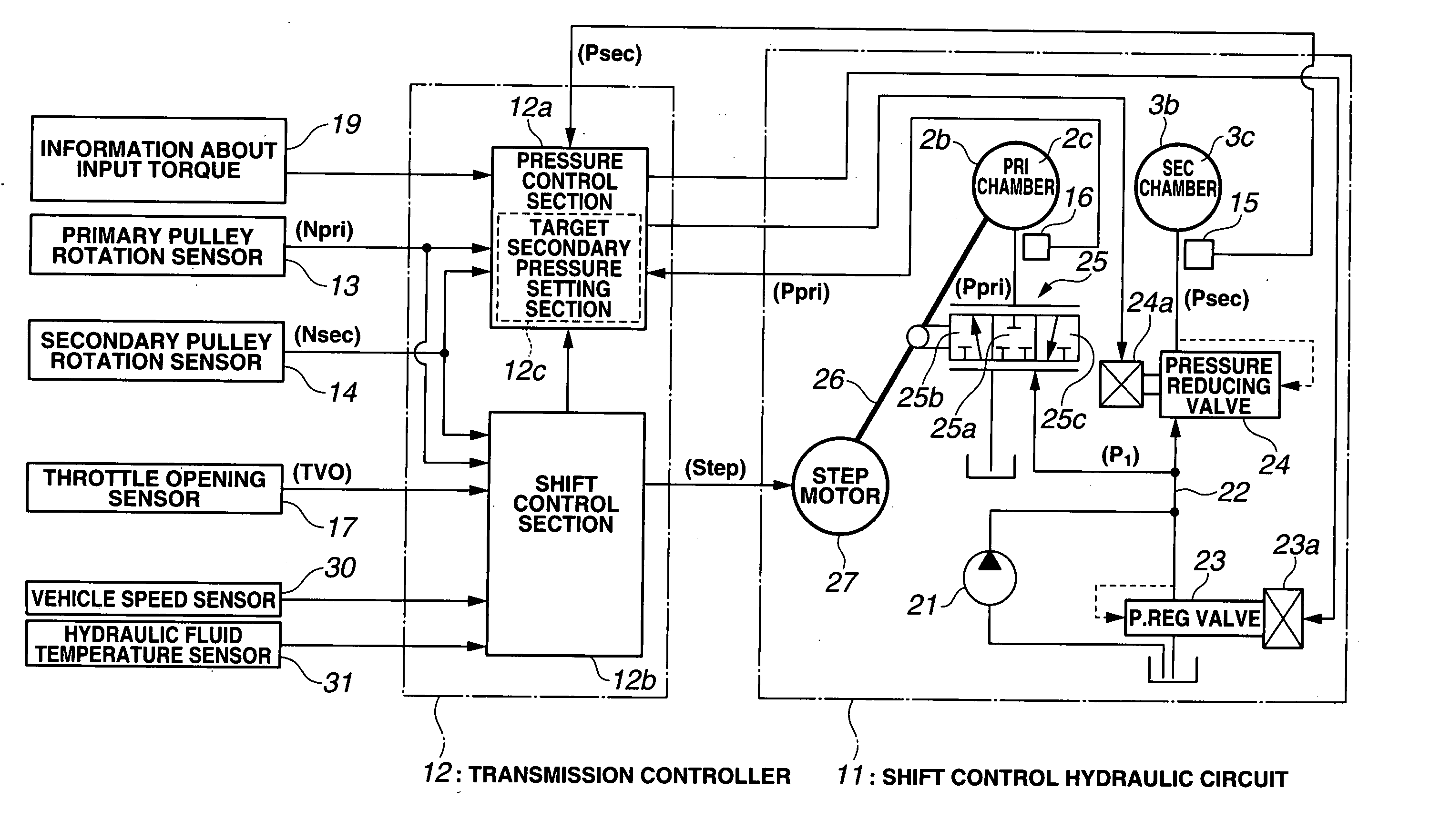
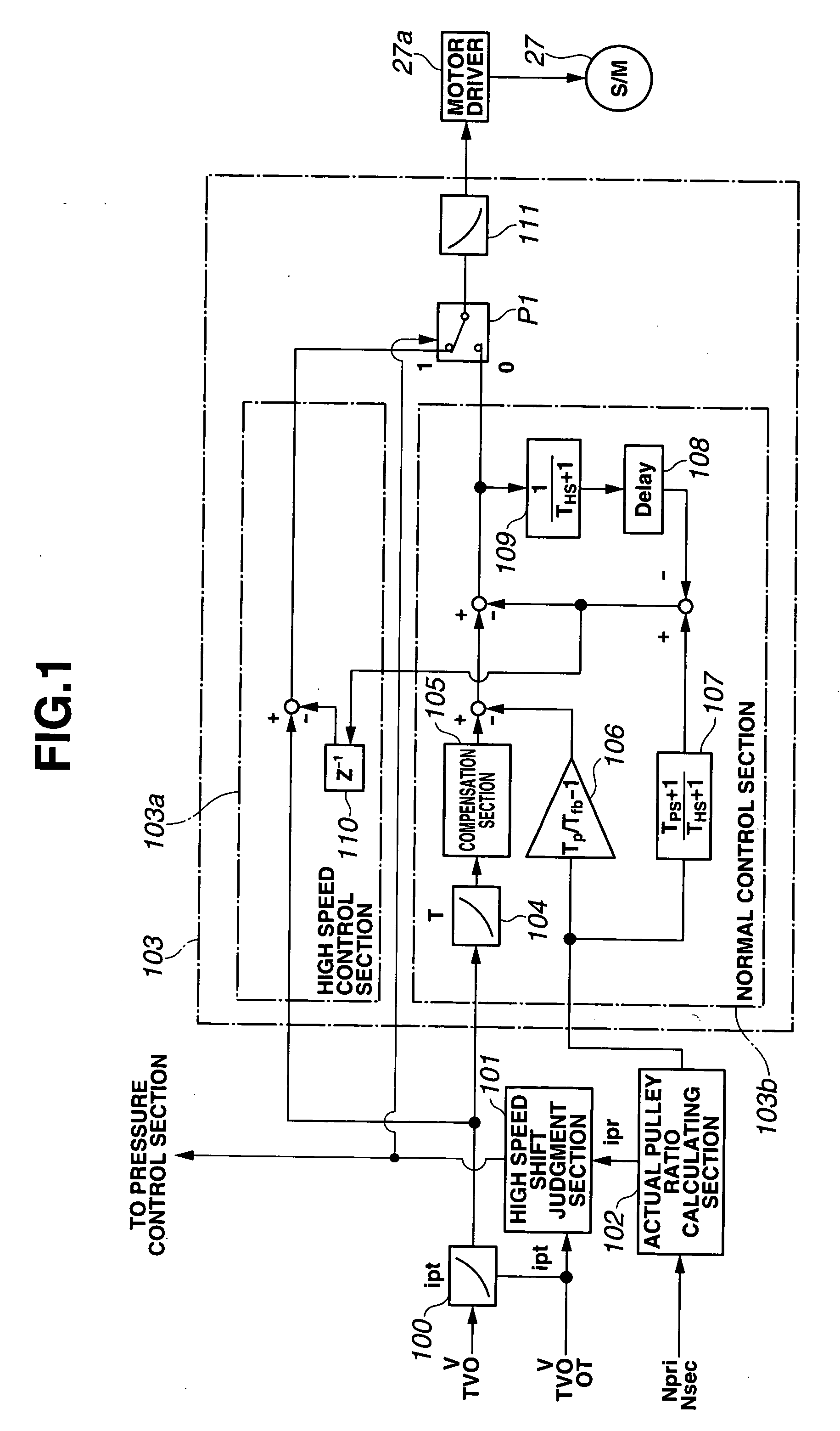
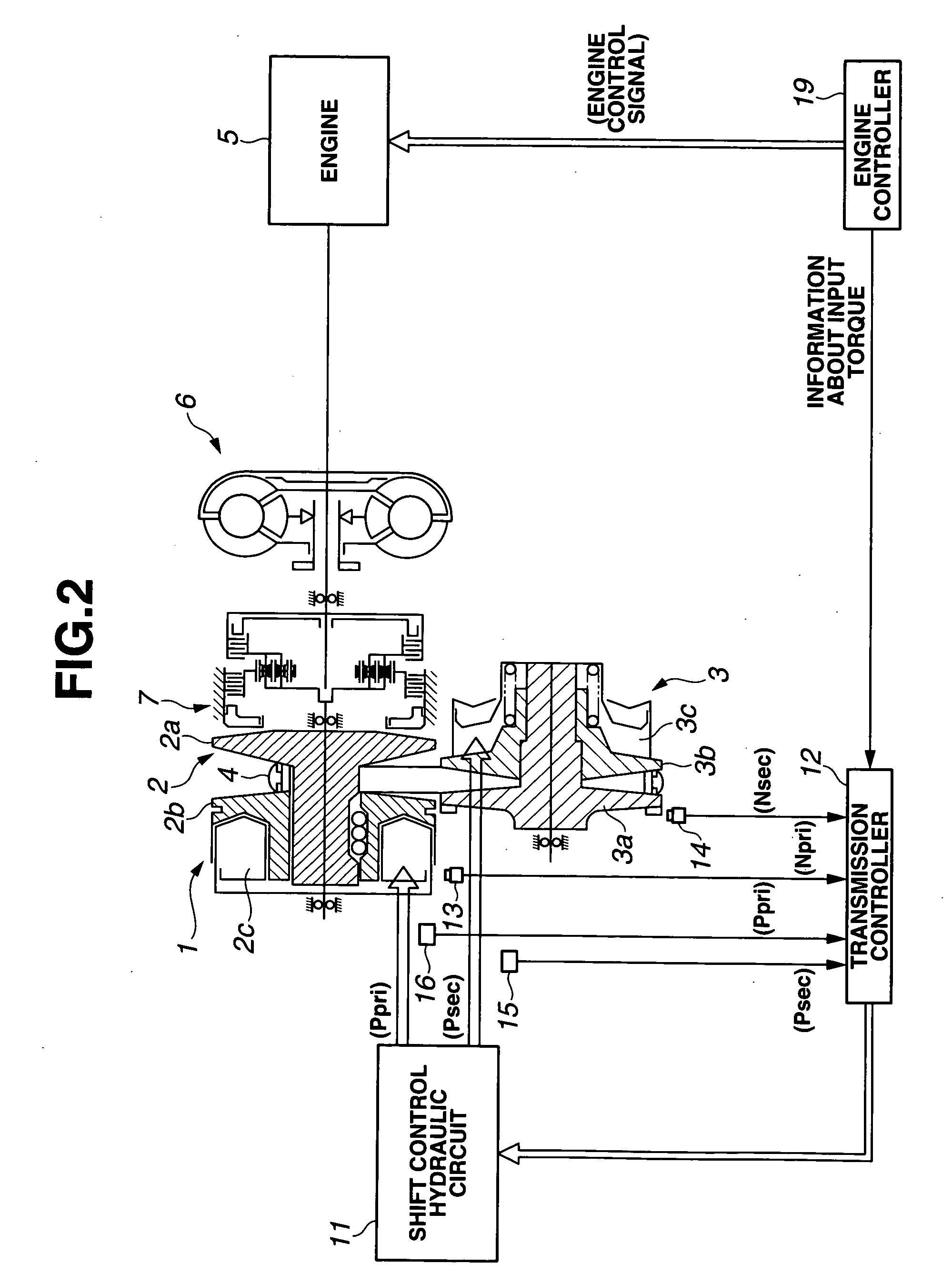
[0021] FIGS. 1˜7 show views illustrative of a hydraulic pressure control apparatus for a belt-type continuously-variable transmission of a vehicle which is employed as a continuously-variable transmission in an embodiment of the present invention. FIG. 1 is a functional block diagram showing a shift control section of a transmission controller configured to control a step motor. FIG. 2 is a diagrammatic view showing the continuously-variable transmission and a shift control system of the continuously-variable transmission. FIG. 3 is a block diagram showing a configuration of a hydraulic pressure control system of the continuously-variable transmission of FIG. 2. FIG. 4 is a circuit diagram showing a hydraulic circuit around a secondary pulley of the transmission of FIG. 2. FIG. 5 is a view showing a section calculating a target secondary pressure. FIG. 6 is a flow chart showing a control process performing by a control system (a high speed shift judgment section). FIG. 7 is a graph ...


PUM


Abstract

A control apparatus for an automatic transmission includes a control section having a target secondary pressure setting section configured to set a target secondary pressure within a strength limit of the belt, and an operation switching section configured to switch a shift operation from a normal speed to a high speed higher than the normal speed when a predetermined condition is satisfied. The control section is configured to control the secondary pressure regulating valve by a feedback control based on the target secondary pressure and the actual secondary pressure sensed by the hydraulic pressure sensor. The target secondary pressure setting section is configured to modify the target secondary pressure by adding a predetermined quantity when a correction initiation condition is satisfied, the condition initiation including a first condition that the shift operation is performed at a high speed by switching of the operation switching section.

Description

BACKGROUND OF THE INVENTION [0001] The present invention relates to a control apparatus for an automatic transmission of a vehicle which is configured to control a transmission gear ratio by using a hydraulic pressure of a hydraulic fluid. [0002] A belt-type continuously-variable transmission includes a primary pulley (driving pulley), a secondary pulley (driven pulley), and a belt wound around the primary pulley and the secondary pulley. The primary pulley includes a fixed pulley (sheave) integrally formed with a shaft (primary shaft) serving as a rotation axis, and a movable pulley (slidable sheave) arranged to be moved in an axial direction of the primary shaft, and located at a position to confront the fixed pulley of the primary pulley. The secondary pulley includes a fixed pulley (sheave) integrally formed with a shaft (secondary shaft) serving as a rotation axis, and a movable pulley (sheave) arranged to be moved in an axial direction of the secondary shaft, and located at a ...

Claims


Application Information

Patent Timeline
IPC IPC(8): F16H59/00F16H61/00
CPCF16H61/66272F16H2061/66281
Inventor YAMAGUCHI, MIDORIKODAMA, YOSHIHISAIIDA, TOSHIJISHIBUYA, TOSHIYUKIOZONE, TATSUYA
Owner JATCO LTD
Learn More