Adjustable Differential Flow Shuttle Valve Control System
- Summary
- Abstract
- Description
- Claims
- Application Information
AI Technical Summary
Benefits of technology
Problems solved by technology
Method used
Image
Examples
embodiment 1
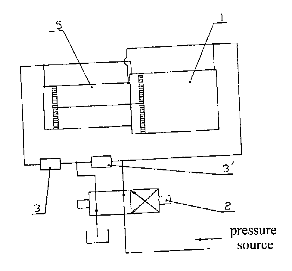
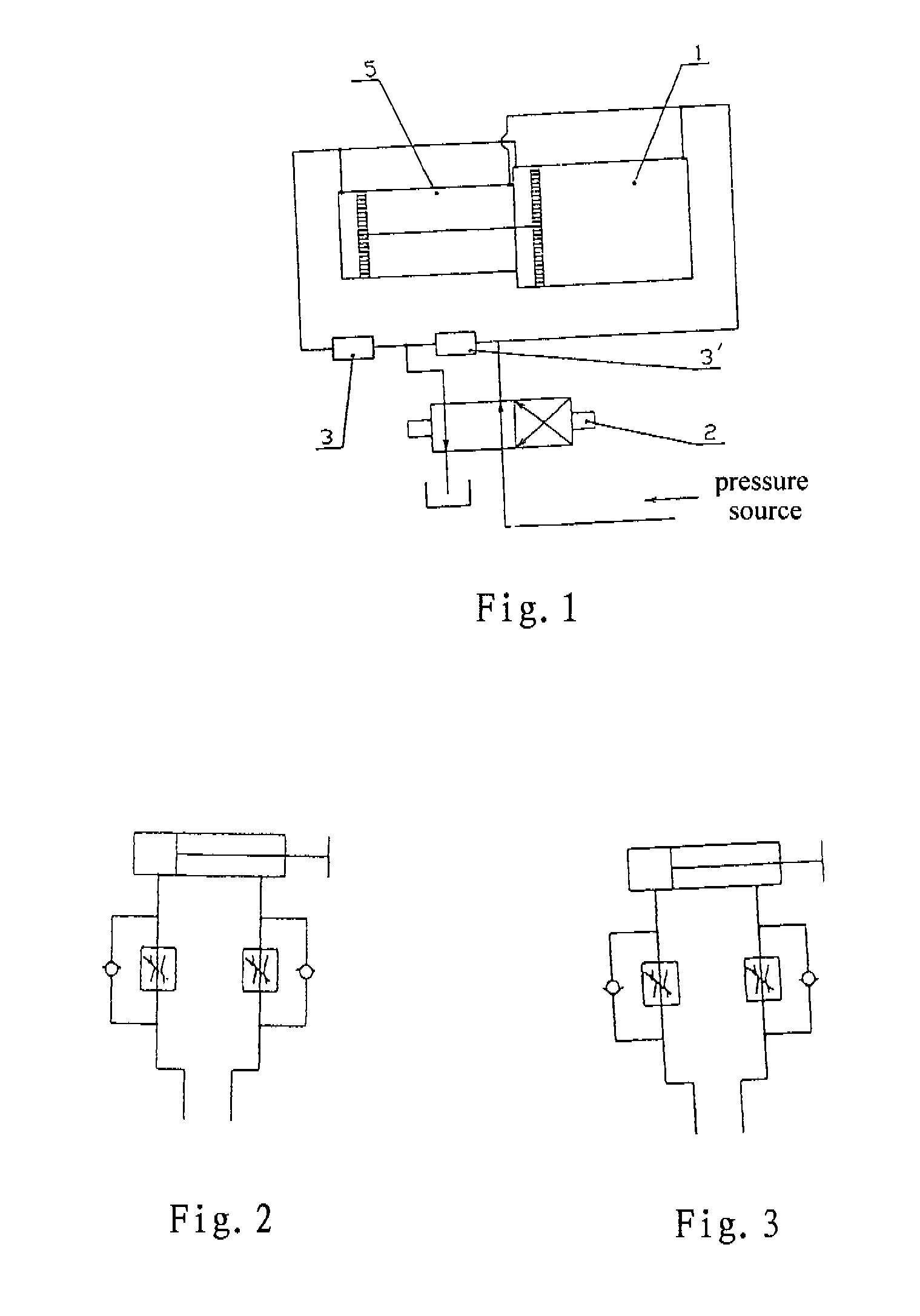
[0032] The first embodiment according to the present invention will be described below with reference to FIG. 1. As shown in FIG. 1, double working cylinders 1 have a common piston rod 5. The piston is positioned at the both ends of the piston rod 5. One end of the double cylinders is connected with one end of the first adjustable differential flow shuttle valve 3 and the medium port of the first working position of a two-position four-way diverter valve 2. The medium is flowed into the diverter valve from the pressure source. The other end of the double cylinders is connected with one end of the second adjustable differential flow shuttle valve 3′. The other ends of the first and second adjustable differential flow shuttle valve are connected with each other, and are connected with another medium port of the first working position of a two-position four-way diverter valve.
[0033] During the operation, at the first working position of the two-position four-way diverter 2, that is, a...
embodiment 2
[0036] First of all, the inflow throttling circuit and the outflow throttling circuit of the prior art will be described in order to have a better understanding of the present invention. As shown in FIG. 2, FIG. 2 shows a control circuit of the prior art having the function of inflow throttling, wherein the first end and the second end of the working cylinder are respectively connected with a throttling valve 3. Moreover, across each throttling valve, a one-way valve 4 is connected, and the one-way valve is arranged to be block in the direction of the medium flowing into the working cylinder, so that the medium must flow into the working cylinder through the throttling valve 3, thereby realizing the function of inlet throttling.
[0037]FIG. 3 shows a control circuit of the prior art having the function of outflow throttling. This control circuit has a substantially same construction as the above-described control circuit having the function of inflow throttling. The difference thereb...
embodiment 3
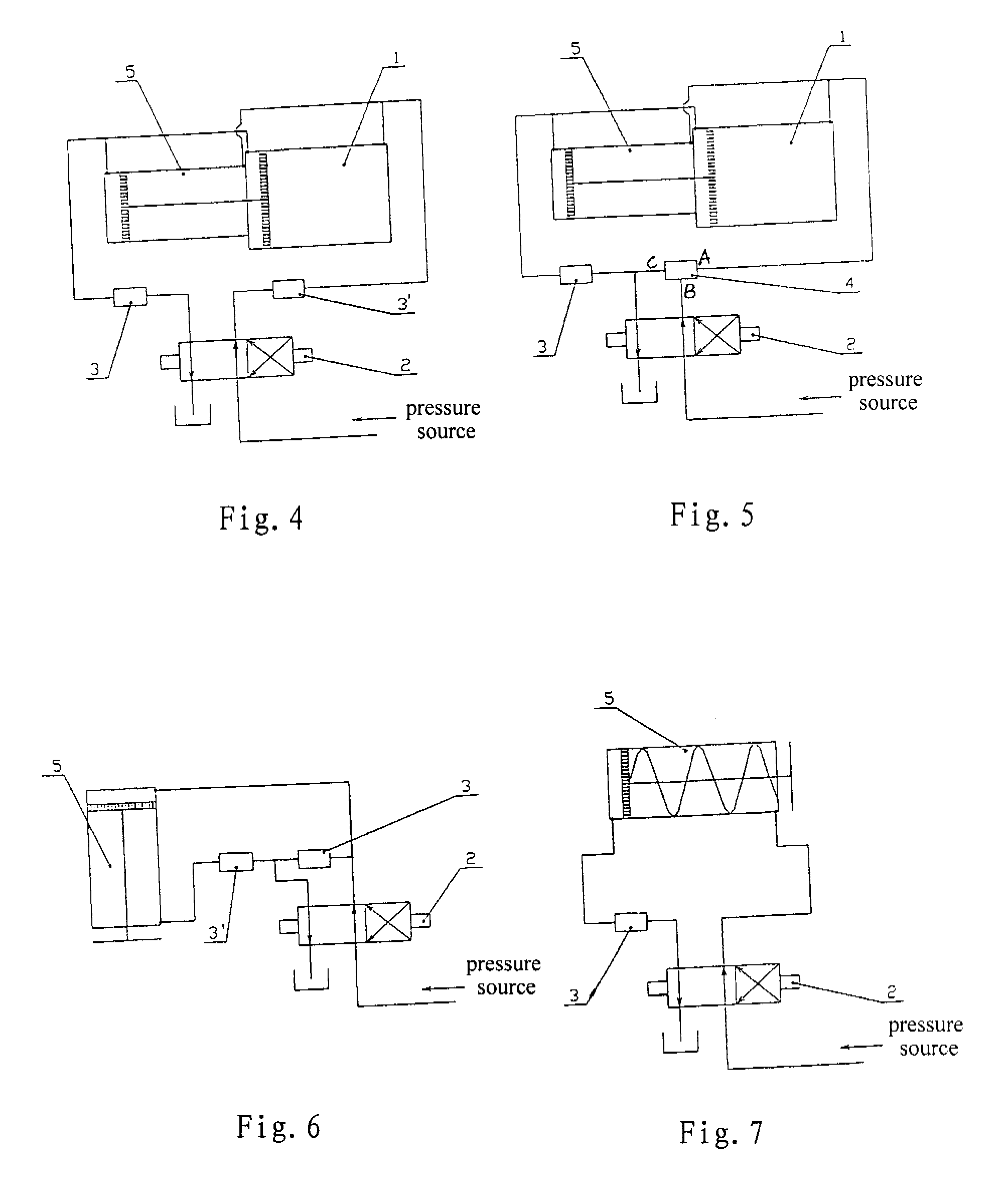
[0041] The control circuit according to the third embodiment of the present invention will be described below with reference to FIG. 5. As shown in FIG. 5, a working cylinder 1 has the same construction as that in the first and second embodiments described above. The right end of the working cylinder is connected with the port A of a shuttle-type three-way diverting regulating valve 4 (referring to FIG. 9). The port B of the three-way diverting regulating valve is connected with the medium outlet end of the first working position of a two-position four-way diverter valve 2. The port C of the diverting regulating valve is connected with one end of an adjustable differential flow shuttle valve 3 and the medium outlet end of the first working position of the two-position four-way diverter valve 2. The other end of the adjustable differential flow shuttle valve 3 is connected the left end of the working cylinder 1.
[0042] During the operation, when the diverter valve 2 is in the first w...
PUM
 Abstract
Description
Claims
Application Information
 - R&D
- Intellectual Property
- Life Sciences
- Materials
- Tech Scout
- Unparalleled Data Quality
- Higher Quality Content
- 60% Fewer Hallucinations
Browse by: Latest US Patents, China's latest patents, Technical Efficacy Thesaurus, Application Domain, Technology Topic, Popular Technical Reports.
© 2025 PatSnap. All rights reserved.Legal|Privacy policy|Modern Slavery Act Transparency Statement|Sitemap|About US| Contact US: help@patsnap.com


