[0035] Yet another
advantage of the present invention is that a traditional
safety valve for 6000 bar may be replaced by a
safety valve for only about 200 bar connected to the low pressure cylinder of the single-
stroke intensifier. A
safety valve for 6000 bar is pretty much for one-time use. Due to the large pressure and flow speed,
cavitation problems will occur and rapidly destroy the safety valve. In the present invention the safety valve will open for the moderate pressure of 200 bar and drain some
hydraulic pressure medium from the low pressure cylinder of the single-stroke intensifier, enabling the pistons to be displaced towards the low pressure side. This means an increase in volume available for the pressurized liquid pressure medium present in the pressure vessel and the high pressure side of the single-stroke intensifier, wherein the pressure is reduced and held at the safety level. The safety valve on the low pressure side may be a conventional overflow valve adapted to hold a pressure of 200 bar, or of course if desirable a higher pressure, such as 300-500 bar.
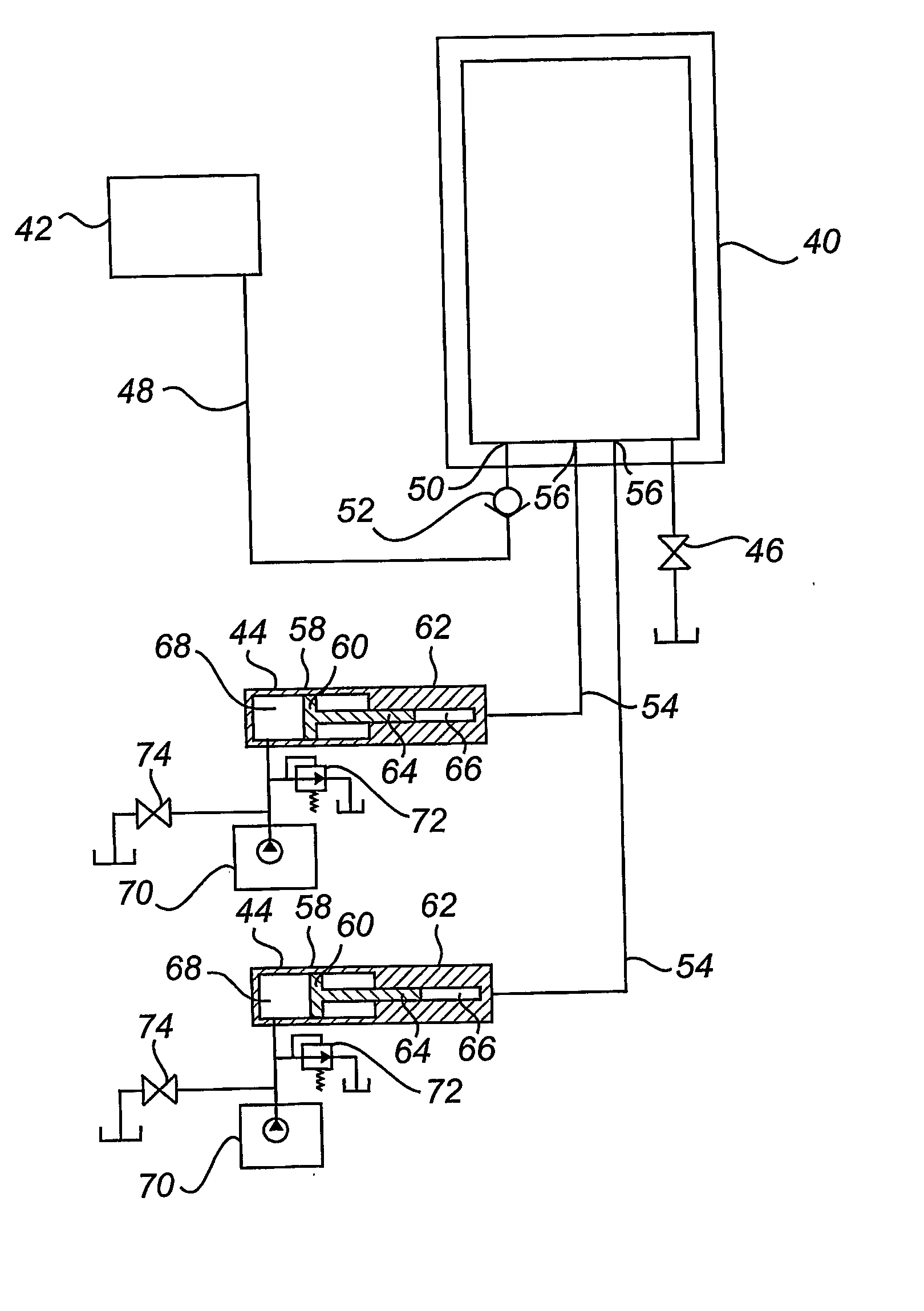
[0036] Just like the safety valve, a draining valve used for reducing the pressure to the
intermediate pressure state may be any valve that is dimensioned for pressures of a couple of hundred bar. Thus, after a finished pressing operation, the draining valve, arranged at the low pressure side of the single-stroke intensifier, is opened so as to drain the
hydraulic pressure medium from the low pressure cylinder, thereby decreasing the pressure in the pressure vessel to the intermediate pressure state.
[0037] Furthermore, it follows from the above that the pressure may be measured on the low pressure side of the single-stroke intensifier, instead of using a pressure gauge at the pressure vessel.
[0038] From the above, it is clear that, when a single-stroke intensifier is used, it functions as said first pressure changing device in a decompressing act, and as said second pressure changing device in a pressurization act. This double functionality underlines the
advantage of using a single-stroke intensifier.
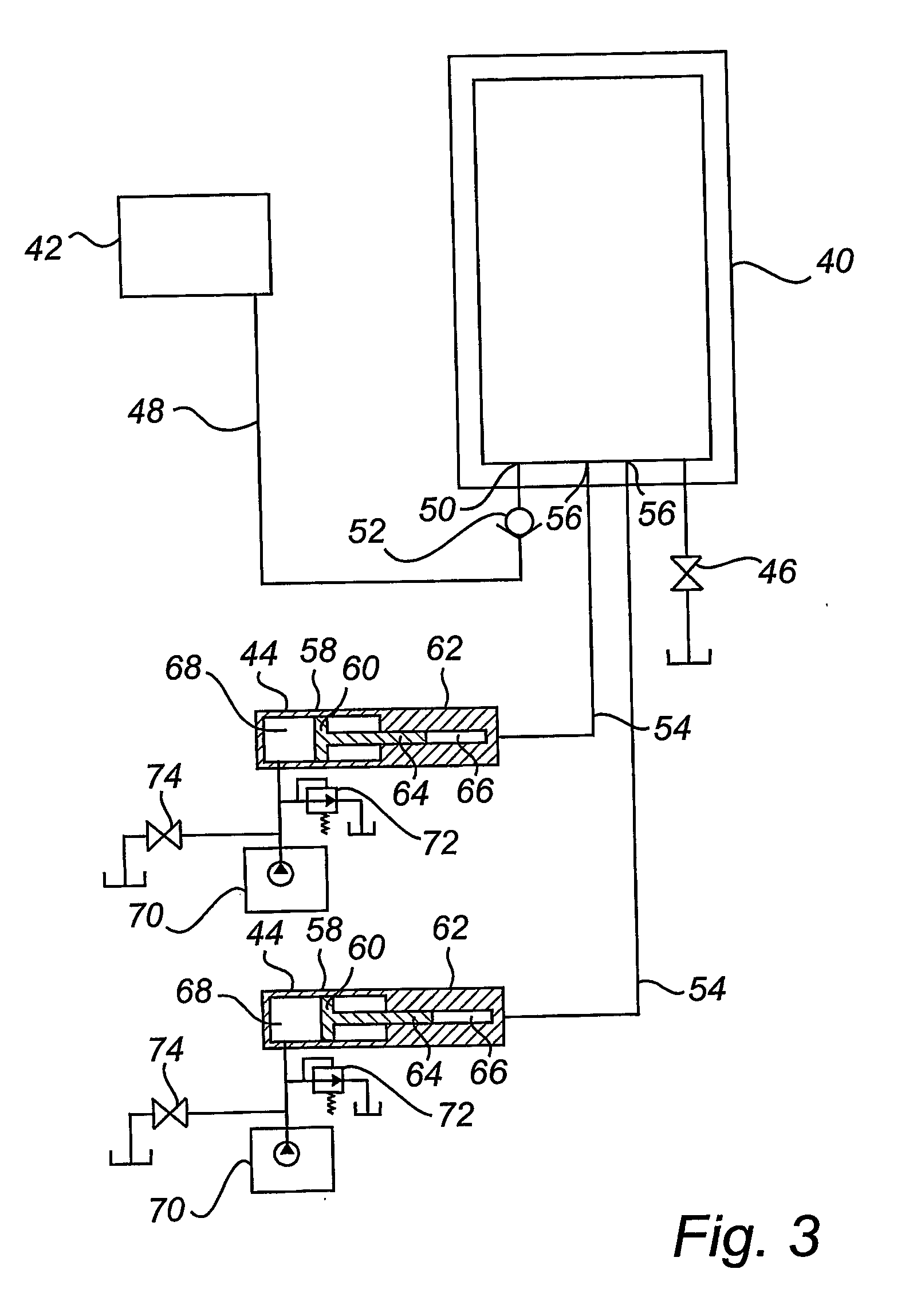
[0039] As an alternative, it would be possible to use two or more single-stroke intensifiers, instead of just one. In such a case they would be operated in parallel or one after the other. One
advantage is that the standard
hydraulic pump does not even have to generate a pressure of 3000-4000 bar, but a lower value would suffice. Correspondingly, in the
decompression operation, the single-stroke intensifiers would enable an effective lowering of pressure in the pressure vessel to a value below 3000-4000 bar. The release valve is thereby even more protected from damage.
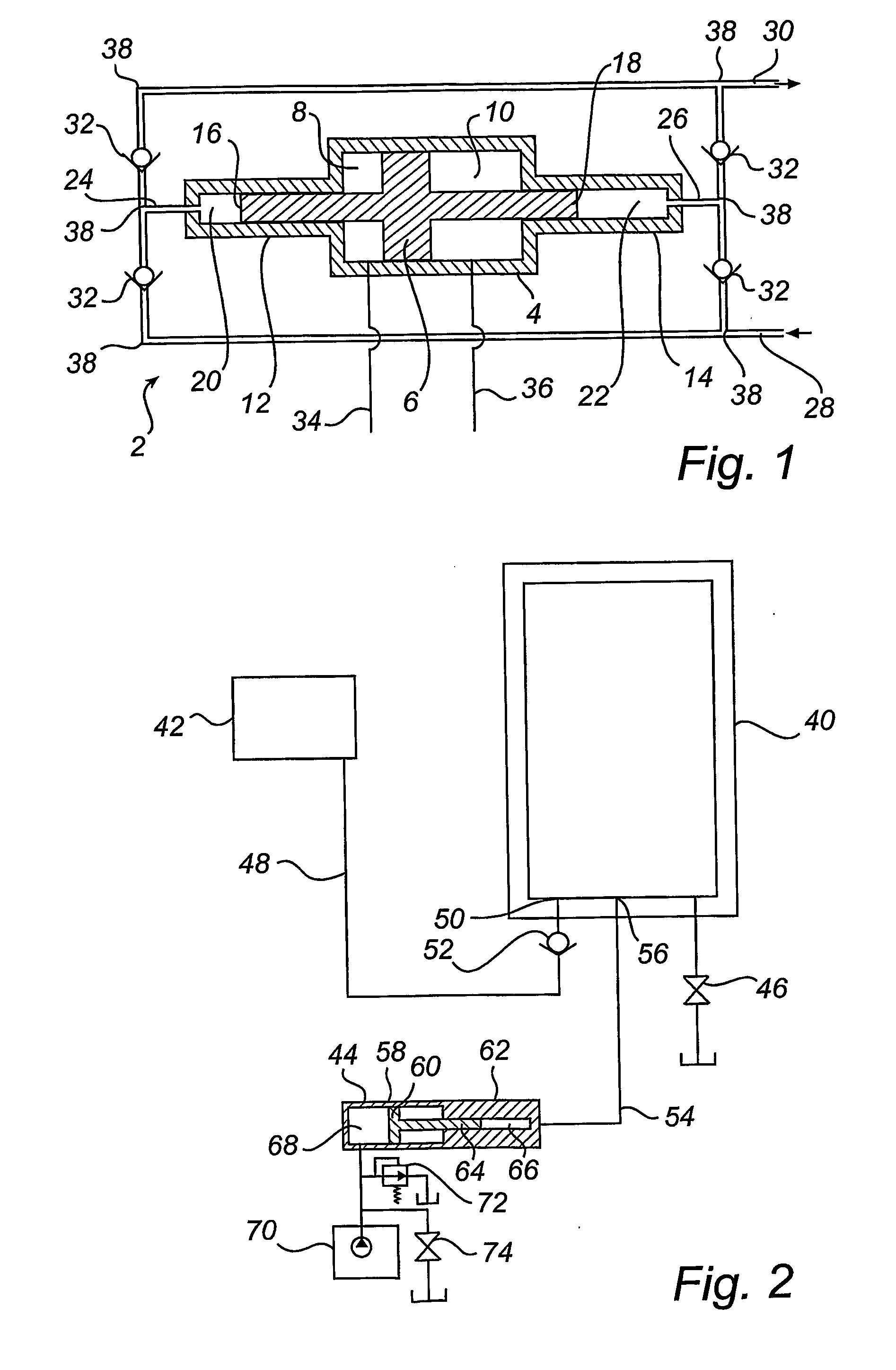
[0040] The connection between the single-stroke intensifier and the pressure vessel may have different dimensions. It may be a narrow conduit or it may be
coupling having a large cross-section. The connection or
coupling may even be as wide as the pressure vessel and / or the single-stroke intensifier. In fact, the pressure intensifier and the pressure vessel may be integrated as a unit. In the
high pressure chamber of the single-stroke intensifier a high pressure
piston is displaceable between a retracted position and an advanced position. The pressure vessel may therefore be regarded as a front portion of the
high pressure chamber of the single-stroke intensifier, i.e. substantially the portion that is left for the liquid pressure medium when the high pressure
piston is in the advanced position providing an increased pressure, relative to the retracted position, in the
high pressure chamber. The rest of the high pressure chamber, i.e. the portion extending between the retracted position and advanced position of the high pressure
piston, may be regarded as comprising a pressure changing device in which the piston is movable. Thus, in the case of pressurization said portion would correspond to the second pressure changing device as previously described. In the case of decompression, said portion would correspond to the first pressure changing device. The connection between the single-stroke intensifier and the pressure vessel corresponds in this case to the wall of the single-stroke intensifier. Even though the above example is an integrated unit, it is also possible to connect two separate units, i.e. a single-stroke intensifier and a pressure vessel, which have substantially the same internal cross-section. The invention solves the problem of
compressibility of liquid pressure medium regardless of the volume of the pressure vessel, which may be a small pressure vessel, such as 30 dm3, or a large pressure vessel, such as 300 dm3. In either case, an extra volume in addition to the total volume of the pressure vessel, is to be forced into the pressure vessel to attain the operating high pressure state. This extra volume is a defined percentage of the total volume.

