Embedded chip antenna having complementary radiator structure

a radiator structure and chip antenna technology, applied in the direction of helical antennas, non-resonant long antennas, protective material radiating elements, etc., can solve the problems of degrading the antenna performance, reducing the specific absorption rate (sar), and muted telephone conversation, so as to reduce the distortion and degradation of antenna characteristics and improve call performance.

Inactive Publication Date: 2007-06-28
ACE ANTENNA
View PDF7 Cites 6 Cited by
  • Summary
  • Abstract
  • Description
  • Claims
  • Application Information

AI Technical Summary

Benefits of technology

[0016]Accordingly, the present invention has been made keeping in mind the above problems occurring in the prior art, and an object of the present invention is to provide an embedded chip antenna having a complementary radiator structure wh...

Problems solved by technology

Such an antenna is advantageous in that it realizes a high gain, but is disadvantageous in that the Specific Absorption Rate (SAR), which is a measure of the influence of electromagnetic waves on the human body, is high because the antenna is non-directional.
However, in the structures of a PIFA and a chip antenna, the antennas are affected by a user's finger or hand when the user is ...

Method used


Image

  • Embedded chip antenna having complementary radiator structure
  • Embedded chip antenna having complementary radiator structure
  • Embedded chip antenna having complementary radiator structure

Examples


first embodiment

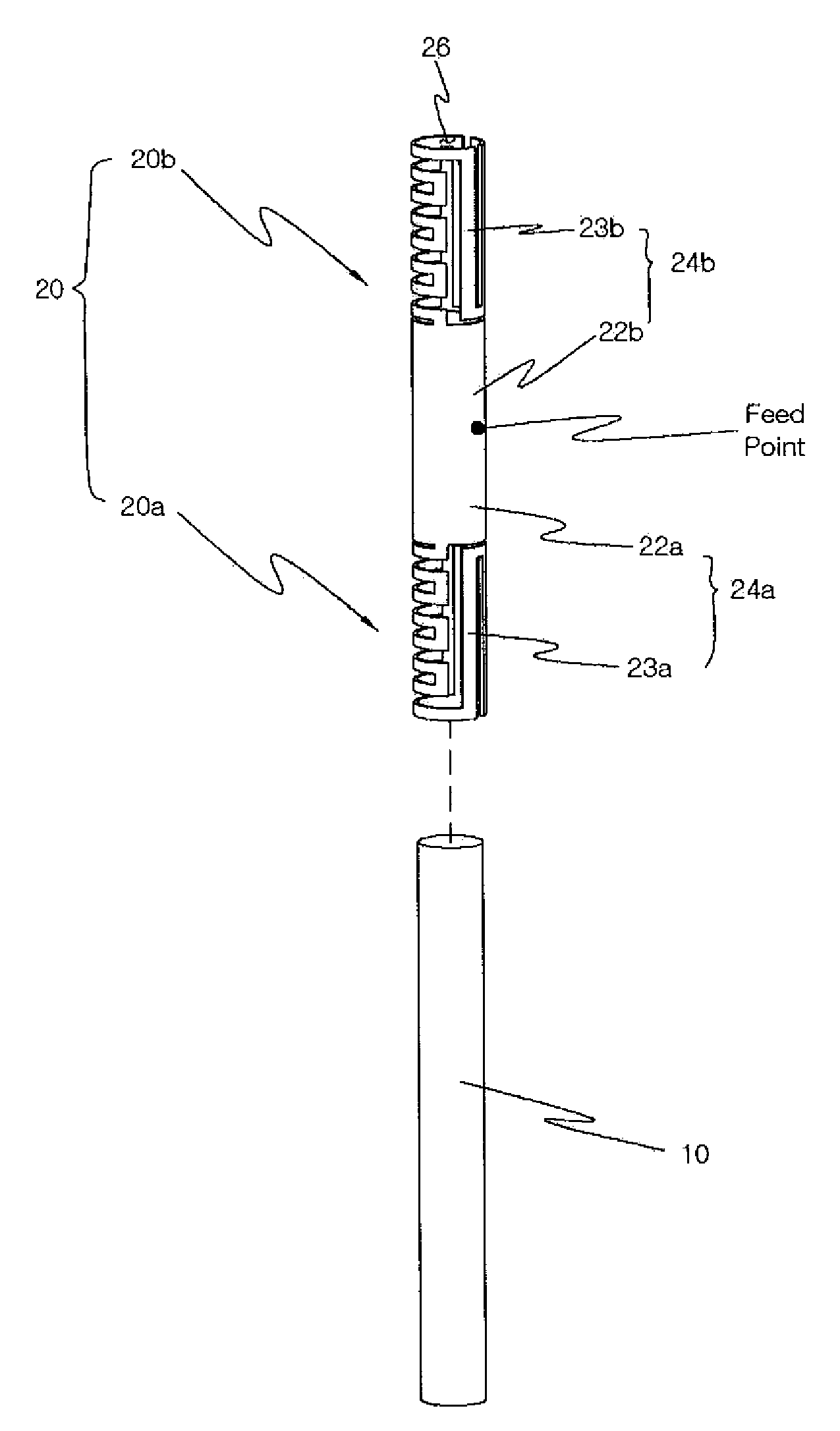
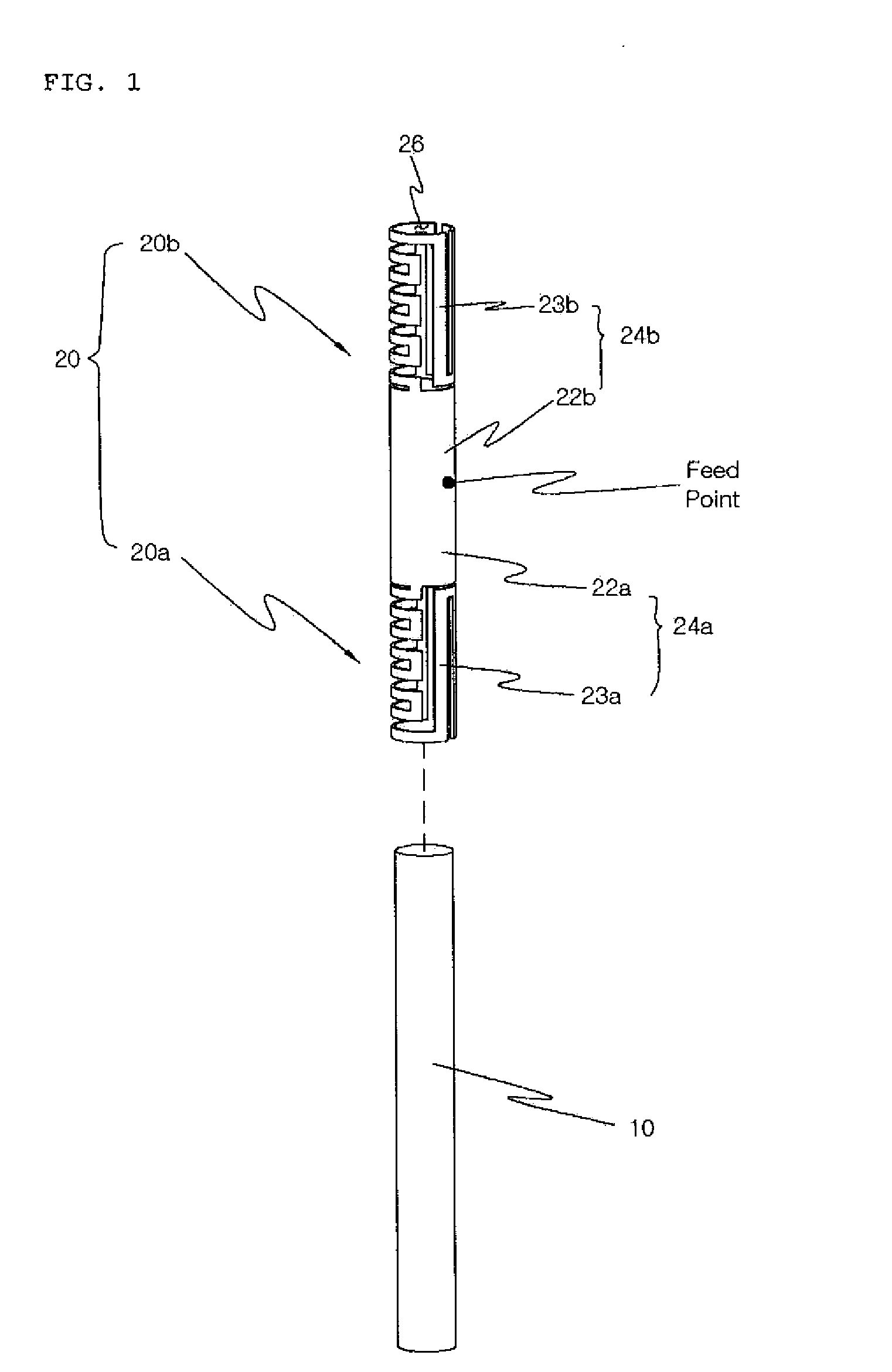
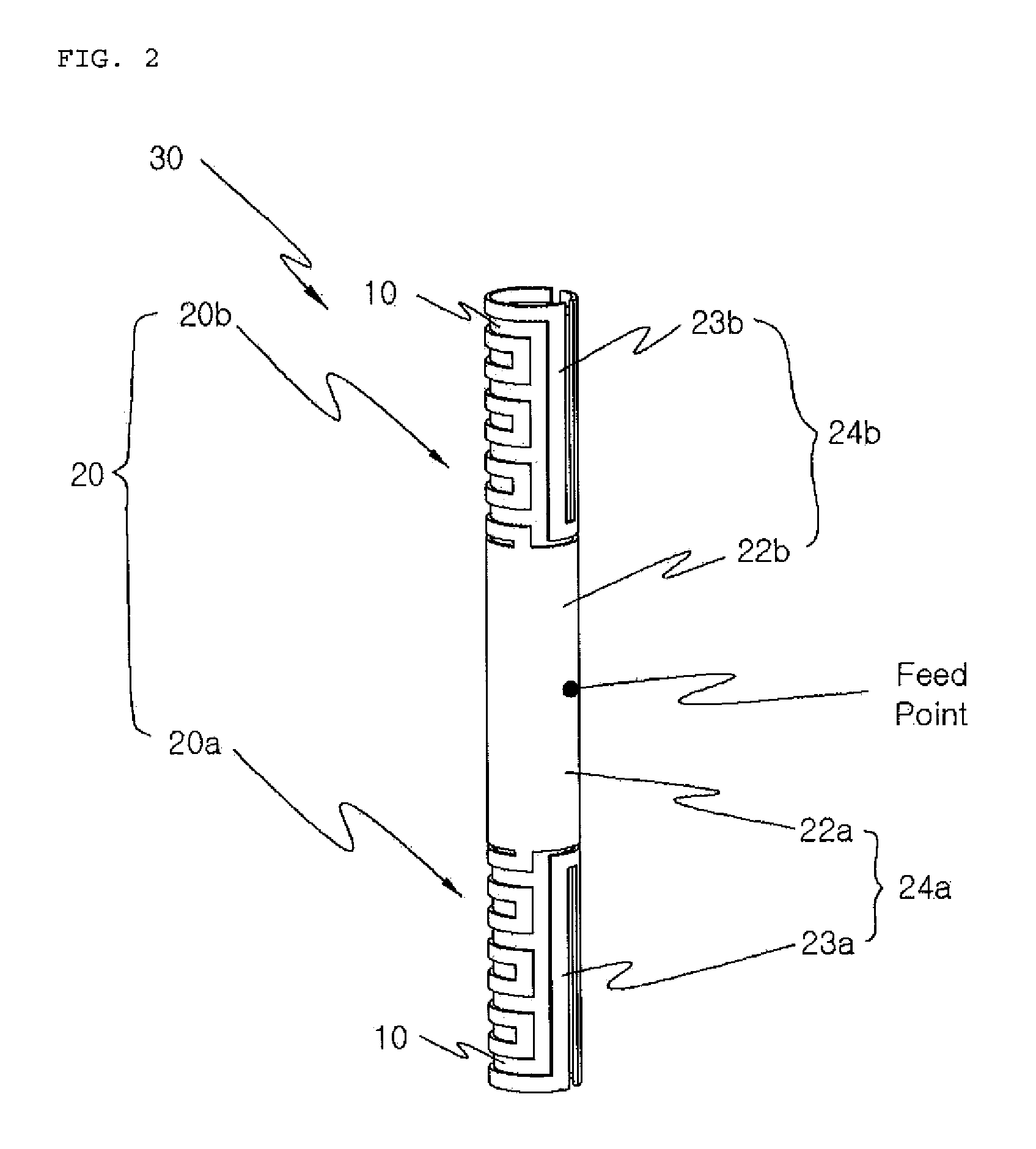
[0028]FIG. 1 is an exploded perspective view of an embedded chip antenna according to the present invention, and FIG. 2 is a perspective assembled view illustrating the embedded chip antenna of FIG. 1.

[0029]Although, in the embodiments of the present invention, a chip antenna having dual-band characteristics will be described for convenience of description, it is also noted that the present invention can be applied to a chip antenna having single-band characteristics.

[0030]As illustrated in FIGS. 1 and 2, a radiator 20 includes first and second partial radiators 20a and 20b. That is, the first radiator 20a and the second radiator 20b, each of which includes a first radiation part 22a or 22b and a second radiation part 24a or 24b, are arranged symmetrically with respect to a feed point.

[0031]Each of the second radiation parts 24a and 24b includes the first radiation part 22a or 22b, and an extended radiation part 23a or 23b which extends from the first radiation part 22a or 22b.

[003...

second embodiment

[0045]FIG. 3 is a perspective assembled view of an embedded chip antenna according to the present invention.

[0046]As illustrated in FIG. 3, a radiator 50 includes first and second partial radiators 50a and 50b. That is, the first radiator 50a and the second radiator 50b, each of which includes a first radiation part 52a or 52b and a second radiation part 54a or 54b, are arranged symmetrically with respect to a feed point.

[0047]Each of the second radiation parts 54a and 54b includes the first radiation part 52a or 52b, and an extended radiation part 53a or 53b which extends from the first radiation part 52a or 52b.

[0048]Therefore, the radiator 50 has the shape of a cylinder having a longitudinal through hole, in which the first radiator 50a and the second radiator 50b, each of which includes the first radiation part 52a or 52b responsible for a high frequency band and the second radiation part 54a or 54b responsible for a low frequency band, are arranged symmetrically to each other....

third embodiment

[0062]FIG. 5 is a perspective assembled view of an embedded chip antenna according to the present invention.

[0063]The technical construction of the present embodiment is different from that of the first embodiment of FIG. 2 in that first radiation parts 122a and 122b responsible for high frequency bands are not cylindrical around a central feed point, and in that second radiation parts 124a and 124b do not respectively extend from the first radiation parts 122a and 122b, but are respectively separate from the first radiation parts 122a and 122b, and the second radiation parts 124a and 124b have meander line structures.

[0064]Since the structure in which partial radiators 120a and 120b are arranged symmetrically with respect to a feed point, the radiation parts 122a and 122b thereof are arranged symmetrically with respect to the feed point, and the radiation parts 124a and 124b thereof are arranged symmetrically with respect to the feed point and a dielectric 110 is embedded in a radi...


PUM


Abstract

Disclosed herein is an embedded chip antenna. The embedded chip antenna having a complementary radiator structure includes two radiators that have identical radiation characteristics and are respectively arranged on both sides of a feed point. According to the present invention, the radiator of a chip antenna has a single physical radiator structure, but is electrically formed of a plurality of partial radiators symmetrical with respect to a feed point, and radiation operations in high and low frequency bands are separately performed. Therefore, complementary operational characteristics that counteract external effects are implemented, so that, when part of a human body, such as the hand, affects one partial radiator on one side of the chip antenna, the other partial radiator on the other side thereof independently operates, thereby minimizing performance degradation originating from the outside of the antenna.

Description

BACKGROUND OF THE INVENTION[0001]1. Field of the Invention[0002]The present invention relates generally to an embedded chip antenna having a complementary radiator structure and, more particularly, to an embedded chip antenna in which dual partial radiators are arranged symmetrically, thereby having complementary characteristics.[0003]2. Description of the Related Art[0004]Currently, mobile communication terminals are being miniaturized and lightened, and, at the same time, are required to provide various types of services.[0005]In order to satisfy this demand, internal circuits and elements used in mobile communication terminals are tending to become multi-functional, and, at the same time, to become gradually miniaturized.[0006]Such a tendency is similarly applied to an antenna, which is one of the principal elements of a mobile communication terminal.[0007]Antennas generally used for such mobile communication terminals include an external helical antenna, an internal Planar Inver...

Claims


Application Information

Patent Timeline
IPC IPC(8): H01Q1/40H01Q5/364
CPCH01Q1/243H01Q1/245H01Q5/364H01Q21/293H01Q1/38H01Q1/24H01Q11/08
Inventor OH, JEONG-KUNYOON, YOUNG-SANGKIM, BYUNG-NAMLEE, SEUNG-YONG
Owner ACE ANTENNA
Why Eureka
Try Eureka