
Illumination optical system, illumination unit and image projection apparatus employing the same

an optical system and illumination unit technology, applied in the direction of lighting and heating apparatus, printing machines, instruments, etc., can solve the problems of deteriorating optical efficiency, poor light distribution, and poor optical efficiency, and achieve the effect of improving optical efficiency

Inactive Publication Date: 2007-07-05
SAMSUNG ELECTRONICS CO LTD
View PDF20 Cites 26 Cited by
  • Summary
  • Abstract
  • Description
  • Claims
  • Application Information

AI Technical Summary

Benefits of technology

[0015]The present invention provides an illumination optical system that is small and in which optical efficiency may be improved even when a light-emitting surface of a light source is relatively large and a light source cannot be regarded as a point light source, and an illumination unit and an image projection apparatus employing the same.
[0019]Additionally, the concave mirror is formed of an aspherical surface such that the concave mirror acts as an aspherical surface of the lens optical system and simultaneously, the emission angle of all on-axis light and off-axis light may be effectively suppressed in a predetermined range. Diverging light from the circumference of the light source (hereinafter, referred to as ‘off-axis light’) greatly deviates from a reflection direction of a diverging light from the center of the light source (hereinafter, referred to as ‘on-axis light’) as the off-axis light is reflected from a reflective surface in the central part that is closer to the optical axis of the concave mirror of the entire light beam. However, because the lens optical system has a larger positive refractive power in the central part than in the circumferential part, large refraction acts on the off-axis light passing the central part of the lens optical system. Thus, the off-axis light that deviates from the reflection direction of the on-axis light is refracted by the reflection optical system so that a difference between the off-axis light and the reflection direction of the on-axis light may be reduced. Thus, the emission angle from the lens optical system of the off-axis light may be suppressed in a predetermined range.
[0021]Accordingly, because the illumination unit of exemplary embodiments of the present invention employs the illumination optical system of exemplary embodiments of the present invention, the same effects as those of the illumination optical system of exemplary embodiments of the present invention are obtained.
[0023]Accordingly, the image projection apparatus of exemplary embodiments of the present invention employs the illumination optical system or the illumination unit of exemplary embodiments of the present invention, the same effects as those of the illumination optical system or the illumination unit of exemplary embodiments of the present invention are obtained.

Problems solved by technology

However, the above-described illumination optical system, the illumination unit using the same, and the image projection apparatus have the following problems.
Thus, a desired light distribution can be obtained when a lamp is a point light source but if the size of the lamp is relatively increased compared to the lens or the reflector, the entire light emitted from all light-emitting surfaces of a so-called surface light source cannot be guided to a direction toward a predetermined angle, and because good light distribution cannot be consequently obtained, optical efficiency is deteriorated.
Thus, when the size of the light source is relatively large, good light distribution cannot be obtained and optical efficiency is deteriorated.
However, because the construction of a lens is complicated or the diameter of an effective lens is increased, the illumination optical system having a small size and good optical efficiency, the illumination unit, and the image projection apparatus employing the same cannot be implemented.

Method used


Image

  • Illumination optical system, illumination unit and image projection apparatus employing the same
  • Illumination optical system, illumination unit and image projection apparatus employing the same
  • Illumination optical system, illumination unit and image projection apparatus employing the same

Examples


first exemplary embodiment

[0036]An illumination optical system according to an exemplary embodiment of the present invention is described together with an illumination unit and an image projection apparatus employing the same.

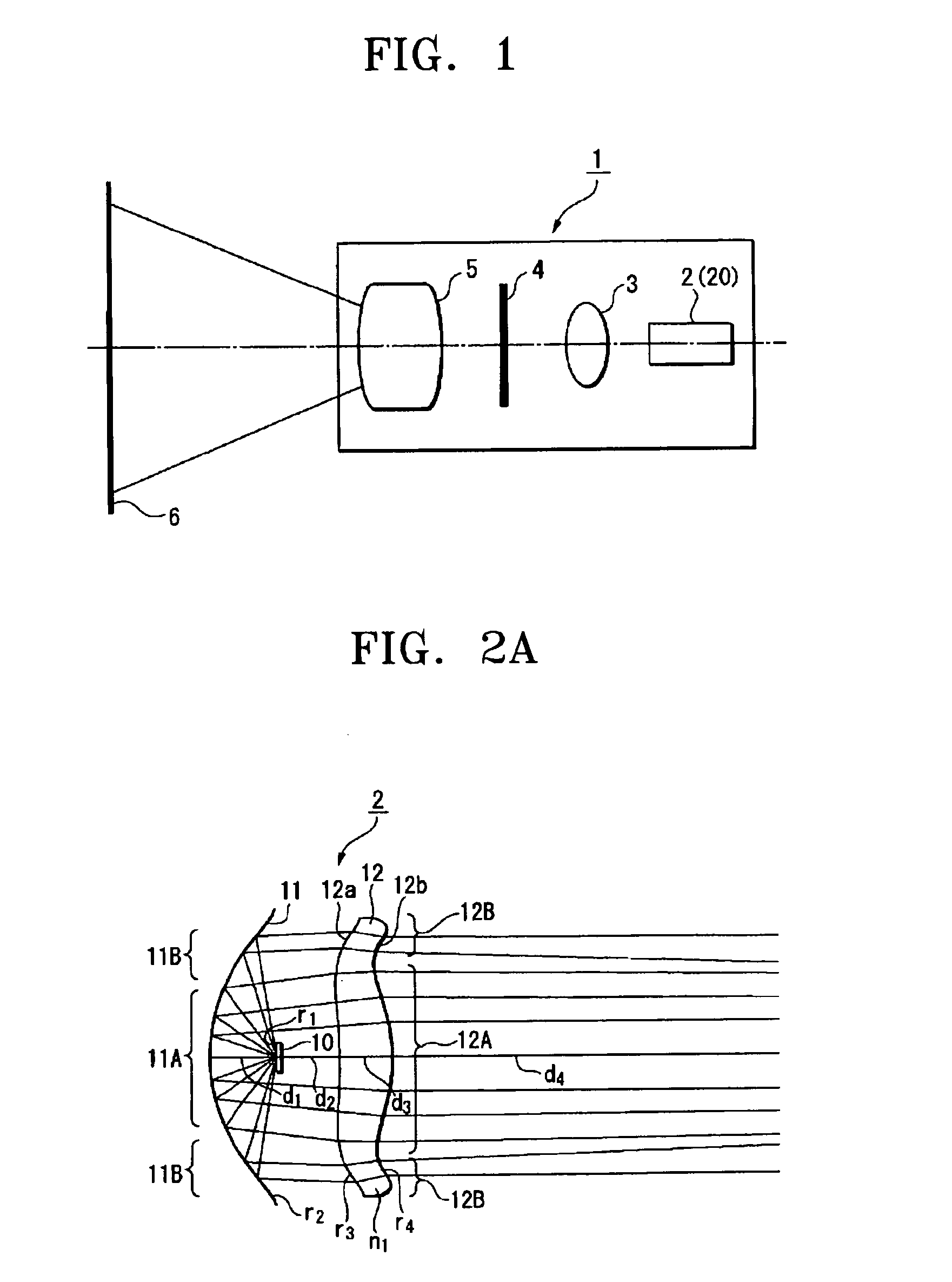
[0037]FIG. 1 is a schematic view of an image projection apparatus using an illumination optical system according to an exemplary embodiment of the present invention.

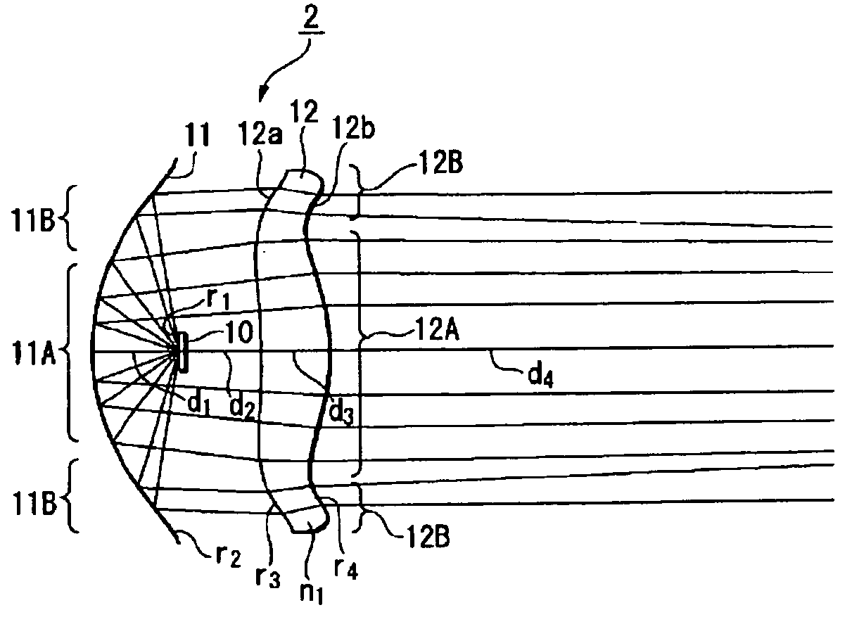
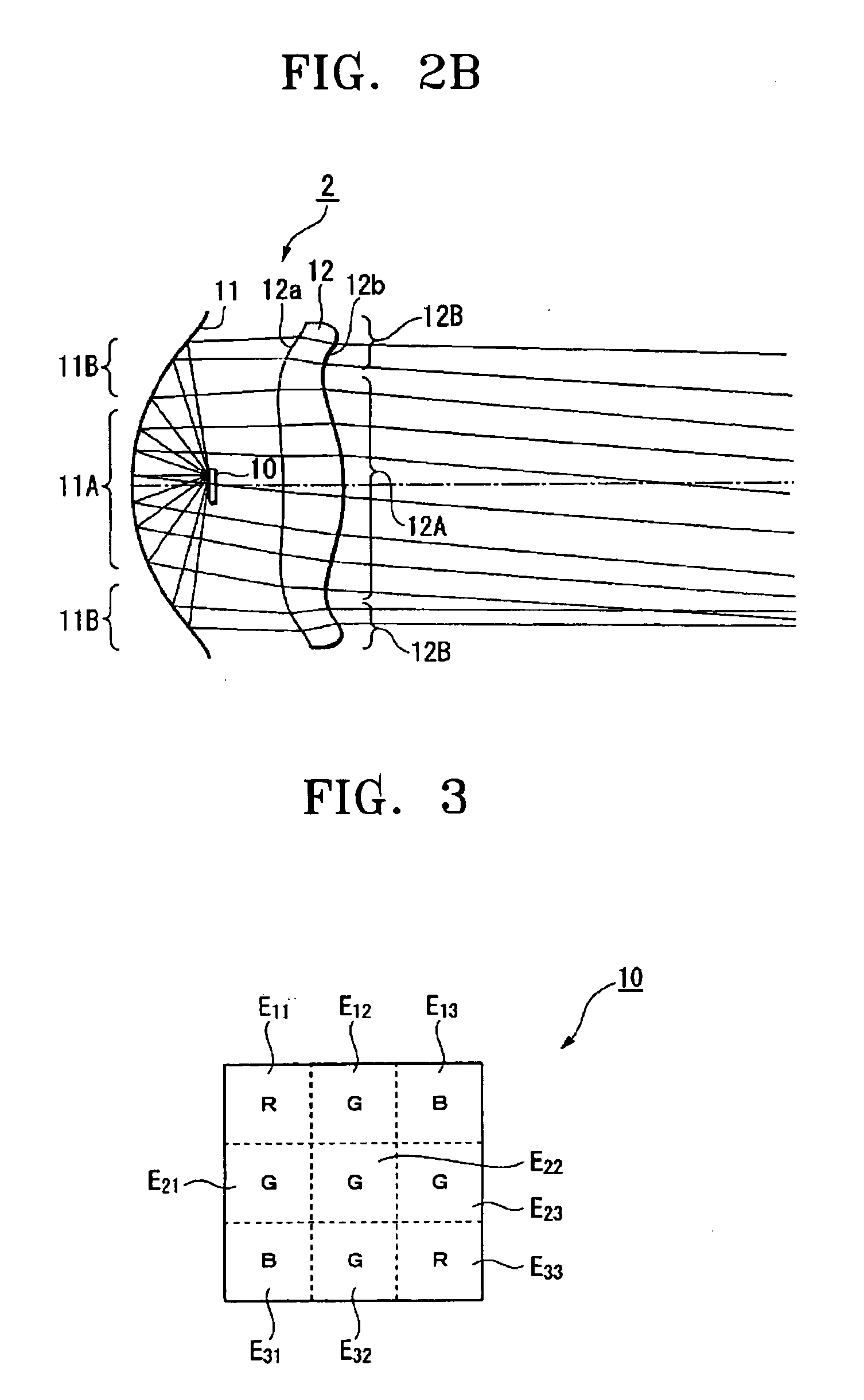
[0038]FIG. 2A illustrates light beams showing a schematic construction of the illumination optical system illustrated in FIG. 1 from a cross-section including an optical axis representing an optical path of on-axis light. FIG. 2B illustrates light beams from a cross-section including an optical axis representing an optical path of off-axis light of the illumination optical system illustrated in FIG. 1. FIG. 3 is a plan view illustrating an example of a light source used in the illumination optical system illustrated in FIG. 1.

[0039]A projector 1 is an image projection apparatus, which includes an illumination unit 2, having ...

second exemplary embodiment

[0098]FIG. 7 illustrates a schematic construction of an image projection apparatus using an illumination optical system according to another exemplary embodiment of the present invention.

[0099]As illustrated in FIG. 7, the schematic construction of a rear projection television 30 according to an exemplary embodiment is comprised of an illumination unit 2, a condensing lens 3, a space modulation element 4, a condensing lens 16, a mirror 17, a projection lens 18, and a transmission type screen 19. Hereinafter, differences between FIGS. 1 and 7 are described.

[0100]The condensing lens 16 and the projection lens 18 are a projection optical system that enlarges and projects a space-modulated image emitted from the space modulation element 4 onto the transmission type screen 19.

[0101]The mirror 17 is an optical deflection unit for folding an optical path of the projection optical system.

[0102]Although not shown, the transmission type screen 19 is formed by stacking a Fresnel lens sheet and...

third exemplary embodiment

[0105]An image projection apparatus according to another exemplary embodiment of the present invention is described below.

[0106]FIG. 8 illustrates a schematic construction of an image projection apparatus using an illumination optical system according to another exemplary embodiment of the present invention.

[0107]As illustrated in FIG. 8, a projector 40 according to an exemplary embodiment includes an illumination unit 21 and an optical path synthesizing unit 22 instead of the illumination unit 2 and the condensing lens 3 of the projector 1 illustrated in FIG. 1. Hereinafter, differences between FIGS. 1 and 8 are described.

[0108]The illumination unit 21 includes illumination optical systems 21R, 21G, and 21B that emit substantially parallel lights of red, green, and blue, respectively. Each illumination optical system replaces an LED 10 or 13 with monochrome LED elements having monochrome LED chips that generate wavelength lights of red, green, and blue in the illumination unit 2 or...


PUM


Abstract

An illumination optical system, an illumination unit, and an image projection apparatus employing the same are provided. The illumination optical system includes a light source irradiating a diverging light, a reflection optical system condensing the diverging light from the light source, and a lens optical system projecting the light condensed by the reflection optical system. The reflection optical system is comprised of an aspherical concave mirror. The lens optical system comprises a condensing lens having a positive refractive power in a central part and a refractive power of the condensing lens being decreased toward a circumferential part. Optical efficiency may be improved even when a light-emitting surface of the light source is relatively large and the light source cannot be regarded as a point light source.

Description

CROSS-REFERENCE TO RELATED PATENT APPLICATIONS[0001]This application claims the benefit under 35 U.S.C. § 119(a) of Japanese Patent Application No. 10-2005-365824, filed on Dec. 20, 2005, in the Japanese Intellectual Property Office, and of Korean Patent Application No. 10-2006-0077779, filed on Aug. 17, 2006 in the Korean Intellectual Property Office, the entire disclosures of both of which are hereby incorporated by reference.BACKGROUND OF THE INVENTION[0002]1. Field of the Invention[0003]The present invention relates to an illumination optical system, an illumination unit, and an image projection apparatus employing the same. More particularly, the present invention relates to an illumination optical system having an improved structure in which light may be effectively condensed even when a light source cannot be regarded as a point light source, an illumination unit, and an image projection apparatus employing the same.[0004]2. Description of the Related Art[0005]Conventionally,...

Claims


Application Information

Patent Timeline
Patent Type & Authority Applications(United States)
IPC IPC(8): F21S8/00
CPCG03B27/545G03B33/06G03B21/208G03B21/2033G02B5/08G02B3/02F21V13/00
Inventor KONUMA, OSAMU
Owner SAMSUNG ELECTRONICS CO LTD
Features
  • Generate Ideas
  • Intellectual Property
  • Life Sciences
  • Materials
  • Tech Scout
  • Unparalleled Data Quality
  • Higher Quality Content
  • 60% Fewer Hallucinations
Learn More