Permanent magnet type motor and x-ray computed tomography apparatus
a permanent magnet type, computed topography technology, applied in the direction of magnetic circuit rotating parts, magnetic circuit shape/form/construction, application, etc., can solve the problems of large x-ray ct apparatus, target requires a mount space and parts, and the cost of assembly is high, and the cost reduction of x-ray ct apparatus is not enough
- Summary
- Abstract
- Description
- Claims
- Application Information
AI Technical Summary
Benefits of technology
Problems solved by technology
Method used
Image
Examples
first embodiment
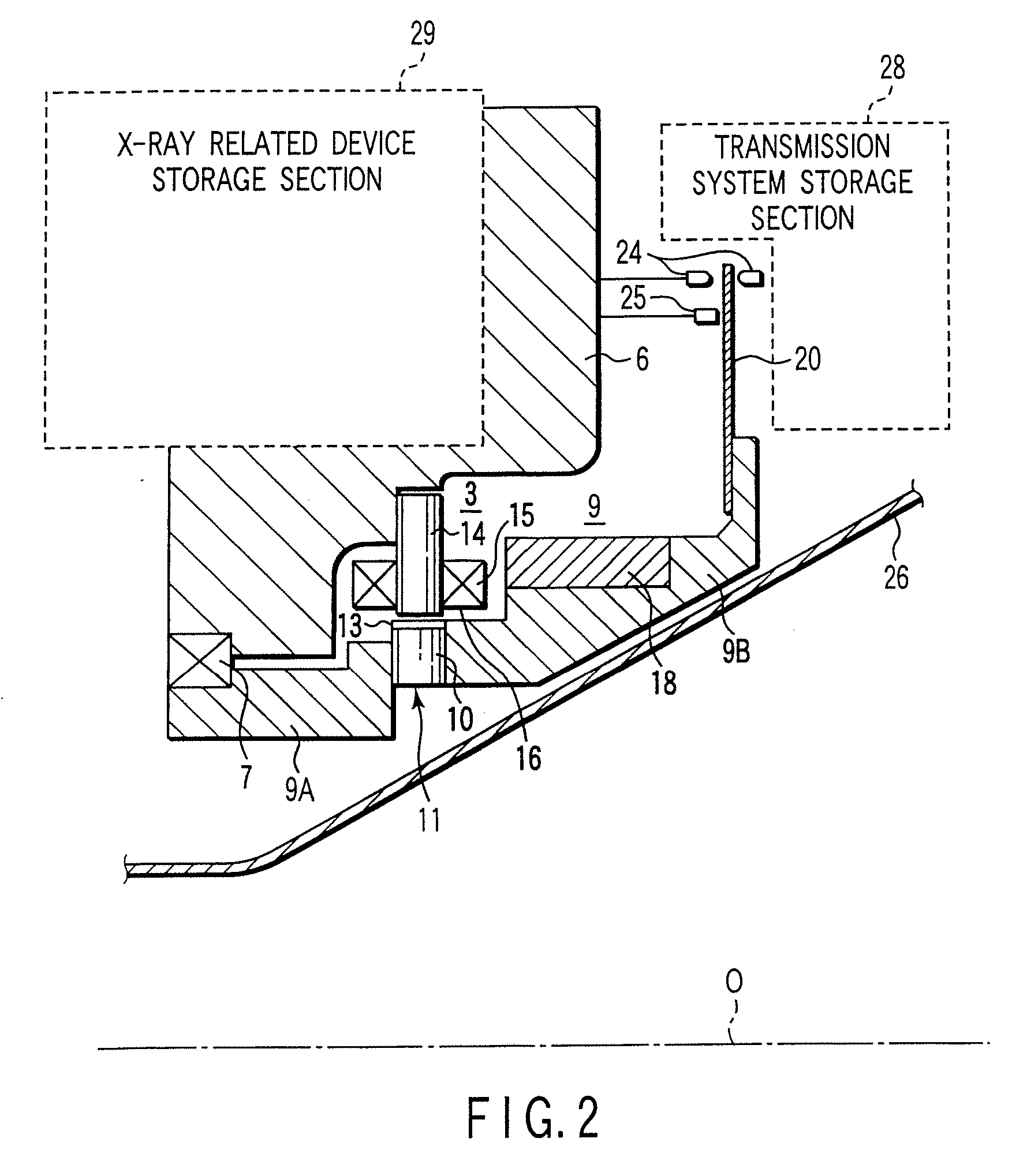
[0044] Now, some embodiments of a permanent magnet type motor according to the present invention other than that shown in FIG. 2 will be described with reference to FIGS. 3A to 10B. FIG. 3A shows a motor layout view and FIG. 3B shows a sectional view taken along the line O-A of FIG. 3A and seen in a direction indicated by the arrows, the views each illustrating the permanent magnet type motor according to the present invention.
[0045] This configuration comprises a ring shaped rotor main body or a rotor yoke 30 rotatably supported by a bearing which is fixed at a stationary frame 6A via a link member (not shown); a plurality of permanent magnets 31 provided on the outer periphery of the rotor main body 30, the magnets 31 having alternately arranged S poles and N poles so that one end part protrudes in an axial direction from the surface of the rotor main body 30, and that the S and N poles are arranged so as to be periodic (equal in interval) in the circular direction; a stator core ...
second embodiment
[0050]FIG. 4A shows another motor layout view illustrating a permanent magnet type motor and FIG. 4B shows a sectional view taken along the line O-A of FIG. 4A and seen in a direction indicated by the arrows. A difference from FIGS. 3A and 3B is that a magnetic sensor 36 is provided in a radial direction of the detection target portion 35, so that the detection target portion 35 is at an end face part of a rotator main body 30. The other configuration is identical to that of FIGS. 3A and 3B and a detailed description thereof may be omitted.
third embodiment
[0051]FIG. 5A shows still another motor layout view illustrating a permanent magnet type motor and FIG. 5B shows a sectional view taken along the line O-A and seen in a direction indicated by the arrows. A difference from FIGS. 4A and 4B is that an irregular portion is not formed as a detection target portion 35 of a rotor main body 30, and instead a plurality of holes 37 are formed periodically (with equal intervals) in a peripheral direction at the inner periphery face side of the rotor main body 30. The other configuration is identical to that of FIGS. 4A and 4B.
PUM
 Abstract
Description
Claims
Application Information
 - R&D
- Intellectual Property
- Life Sciences
- Materials
- Tech Scout
- Unparalleled Data Quality
- Higher Quality Content
- 60% Fewer Hallucinations
Browse by: Latest US Patents, China's latest patents, Technical Efficacy Thesaurus, Application Domain, Technology Topic, Popular Technical Reports.
© 2025 PatSnap. All rights reserved.Legal|Privacy policy|Modern Slavery Act Transparency Statement|Sitemap|About US| Contact US: help@patsnap.com


