
Control device for vehicular drive system

Active Publication Date: 2007-07-05
TOYOTA JIDOSHA KK
View PDF2 Cites 18 Cited by
  • Summary
  • Abstract
  • Description
  • Claims
  • Application Information

AI Technical Summary

Benefits of technology

[0010] The present invention was made in view of the background art described above. It is therefore an object of this invention to provide a control device of a vehicular drive system including a differential mechanism operable to perform a differential function, and a transmission constituting a part of a power transmitting path between the differential mechanism and drive wheels, which control device provides an improvement in the durability of coupling devices provided to switch a power transmitting path between an engine and the drive wheels, between a power-cutoff state and a power-transmitting state.

Problems solved by technology

However, the manual operation from the non-drive position to the drive position has a risk of deterioration of durability of the coupling devices provided for switching of the power transmitting path between the power-cutoff state and the power-transmitting state.
The risk of deterioration increases with an increase of the engine torque to be transmitted.

Method used


Image

  • Control device for vehicular drive system
  • Control device for vehicular drive system
  • Control device for vehicular drive system

Examples


embodiment 1

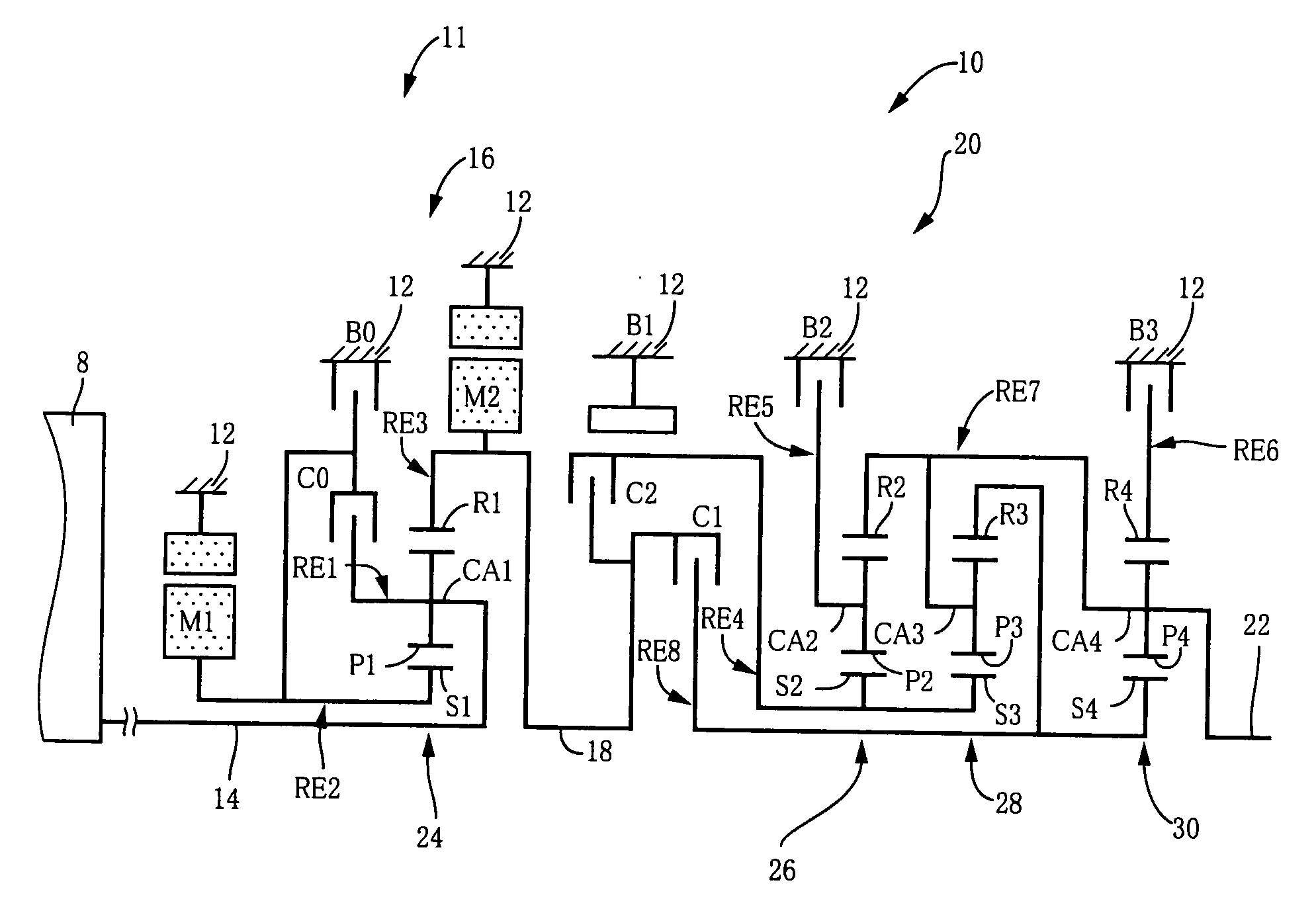
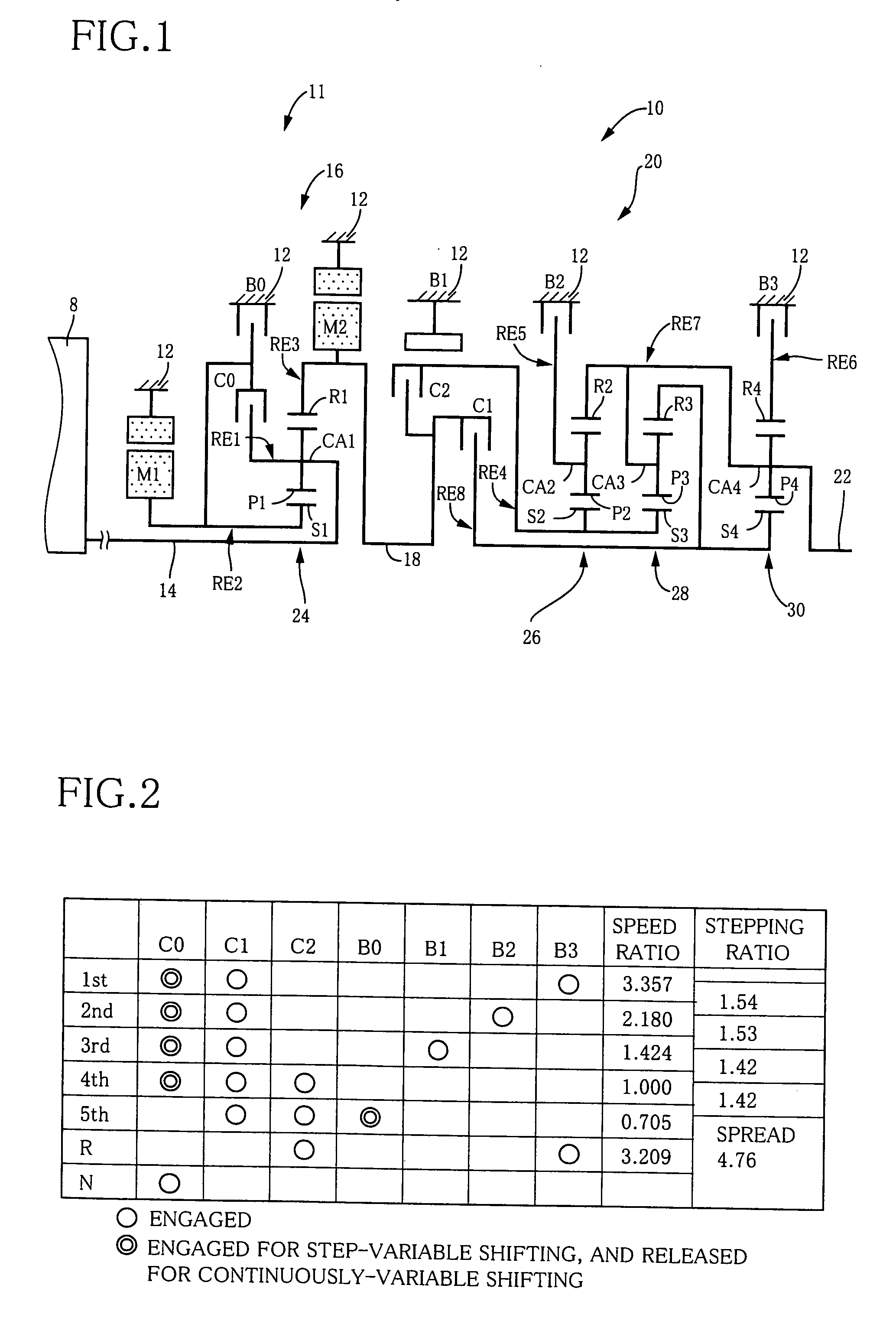
[0040] Referring to the schematic view of FIG. 1, there is sown a drive mechanism 10 constituting a part of a drive system for a hybrid vehicle, which drive system is controlled by a control device according to one embodiment of this invention. As shown in FIG. 1, the transmission mechanism 10 includes an input rotary member in the form of an input shaft 14, a differential portion 11, an automatic transmission portion 20, and an output rotary member in the form of an output shaft 22, which are disposed on a common axis in a transmission casing 12 functioning as a stationary member attached to a body of the vehicle. The differential portion 11 is connected to the input shaft 14 either directly, or indirectly via a pulsation absorbing damper (vibration damping device) not shown. The automatic transmission portion 20 is a transmission portion functioning as a step-variable transmission interposed in a power transmitting path between the differential portion 11 and drive wheels 38, and ...

embodiment 2

[0113] In the present embodiment, the above-described electric-motor control means 86 is arranged to command the hybrid control means 52 to place the first electric motor M1 and the second electric motor M2 in the non-load state for thereby inhibiting the control of the engine speed NE by controlling the first and second electric motors M1, M2, for the purpose of reducing the deterioration of durability of the first clutch C1 and / or the second clutch C2 upon the manual operation of the shift lever 48 from the non-drive position to the drive position, when it is determined by the accelerator-operation determining portion 82 that the accelerator pedal 45 has been operated while the shift lever 48 is placed in the non-drive position, that is, while it is determined by the shift-position determining portion 80 that the shift leer 48 is placed in the neutral position N or parking position P. According to the command received from the electric-motor control means 86, the hybrid control me...

embodiment 3

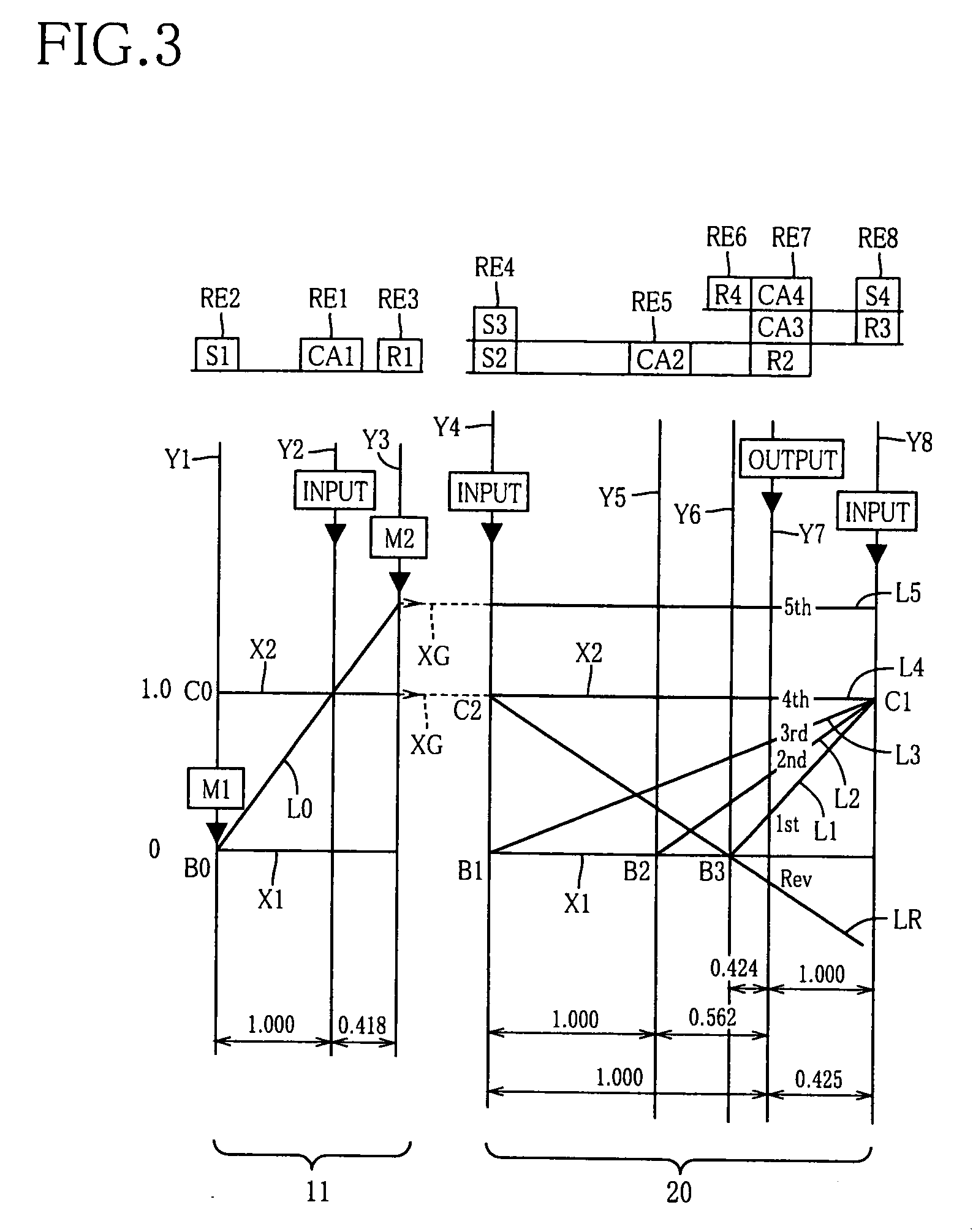
[0117]FIG. 12 is a schematic view showing an arrangement of a transmission mechanism 70 according to a further embodiment of the present invention, and FIG. 13 is a table indicating gear positions of the transmission mechanism 70, and different combinations of engaged states of the hydraulically operated frictional coupling devices for respectively establishing those gear positions, while FIG. 14 is a collinear chart for explaining a shifting operation of the transmission mechanism 70.

[0118] The transmission mechanism 70 includes the differential portion 11 having the first electric motor M1, power distributing mechanism 16 and second electric motor M2, as in the first embodiment. The transmission mechanism 70 further includes an automatic transmission portion 72 having three forward drive positions. The automatic transmission portion 72 is disposed between the differential portion 11 and the output shaft 22 and is connected in series to the differential portion 11 and output shaft...


PUM


Abstract

A control device for a vehicular drive system including (a) a differential portion having a differential mechanism operable to distribute an output of an engine to a first electric motor and a power transmitting member, and a second electric motor disposed in a power transmitting path between the power transmitting member and a drive wheel of a vehicle, (b) a transmission portion which constitutes a part of the power transmitting path, (c) a coupling device operable to place a power transmitting path between the engine and the drive wheel, selectively in a power-transmitting state or a power-cutoff state, and (d) a shift lever operable between a drive position for the coupling device to select the power-transmitting state, and a non-drive position for the coupling device to select the power-cutoff state, the control device including an engine-speed control device for controlling engine speed NE so as not to exceed a predetermined engine speed value NE′ while the shift lever is placed in the non-drive position, so that the coupling device is engaged while engine torque TE is reduced as a result of an operation of the shift lever from the non-drive position to the drive position, whereby the durability of the coupling device is improved.

Description

BACKGROUND OF THE INVENTION [0001] 1. Field of the Invention [0002] The present invention relates to a control device for a vehicular drive system, and more particularly to a vehicular drive system which includes a differential mechanism operable to perform a differential function, and a transmission constituting a part of a power transmitting path between the differential mechanism and drive wheels, and which is improved in the durability of coupling devices provided to switch a power transmitting path between an engine and the drive wheels, between a power-cutoff state and a power-transmitting state. [0003] 2. Discussion of Related Art [0004] There is known a vehicular drive system including a differential mechanism operable to mechanically synthesize forces and distribute a force, and an electric motor operatively connected to the differential mechanism. Examples of this type of vehicular drive system include a drive system for a hybrid vehicle as disclosed in Patent Document 1. ...

Claims


Application Information

Patent Timeline
IPC IPC(8): B60K1/02
CPCB60K1/02Y10T477/23B60K6/40B60K6/445B60K6/547B60W10/02B60W10/06B60W10/08B60W10/115B60W20/00B60W2710/0644F16H3/728F16H2037/0873F16H2200/0043F16H2200/0047F16H2200/201F16H2200/2012F16H2200/2046F16H2200/2048Y02T10/6286Y02T10/6239B60K6/365F16H2200/2007Y02T10/62B60W2510/0638B60W2510/0666
Inventor TABATA, ATSUSHITAGA, YUTAKA
Owner TOYOTA JIDOSHA KK
Features
  • Generate Ideas
  • Intellectual Property
  • Life Sciences
  • Materials
  • Tech Scout
  • Unparalleled Data Quality
  • Higher Quality Content
  • 60% Fewer Hallucinations
Learn More