

Actuator assebmly for prosthetic or orthotic joint
actuator technology, applied in the field of systems and methods for controlling a prosthetic or orthotic joint, can solve the problems of high energy expenditure on the part of the disabled person or amputee, inability to take into account the dynamic conditions of the working environment of the basic controller, and inability to achieve the effect of reducing the risk of injury, and reducing the effect of the patient's li
- Summary
- Abstract
- Description
- Claims
- Application Information
AI Technical Summary
Benefits of technology
Problems solved by technology
Method used
Image

Examples
Embodiment Construction
Related Applications
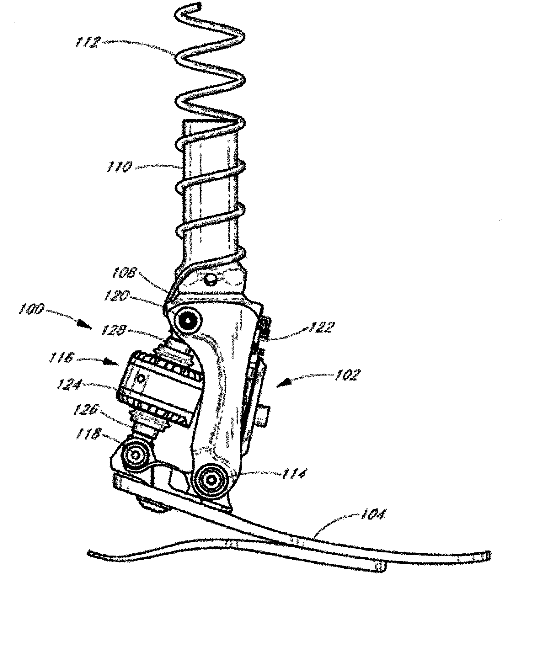
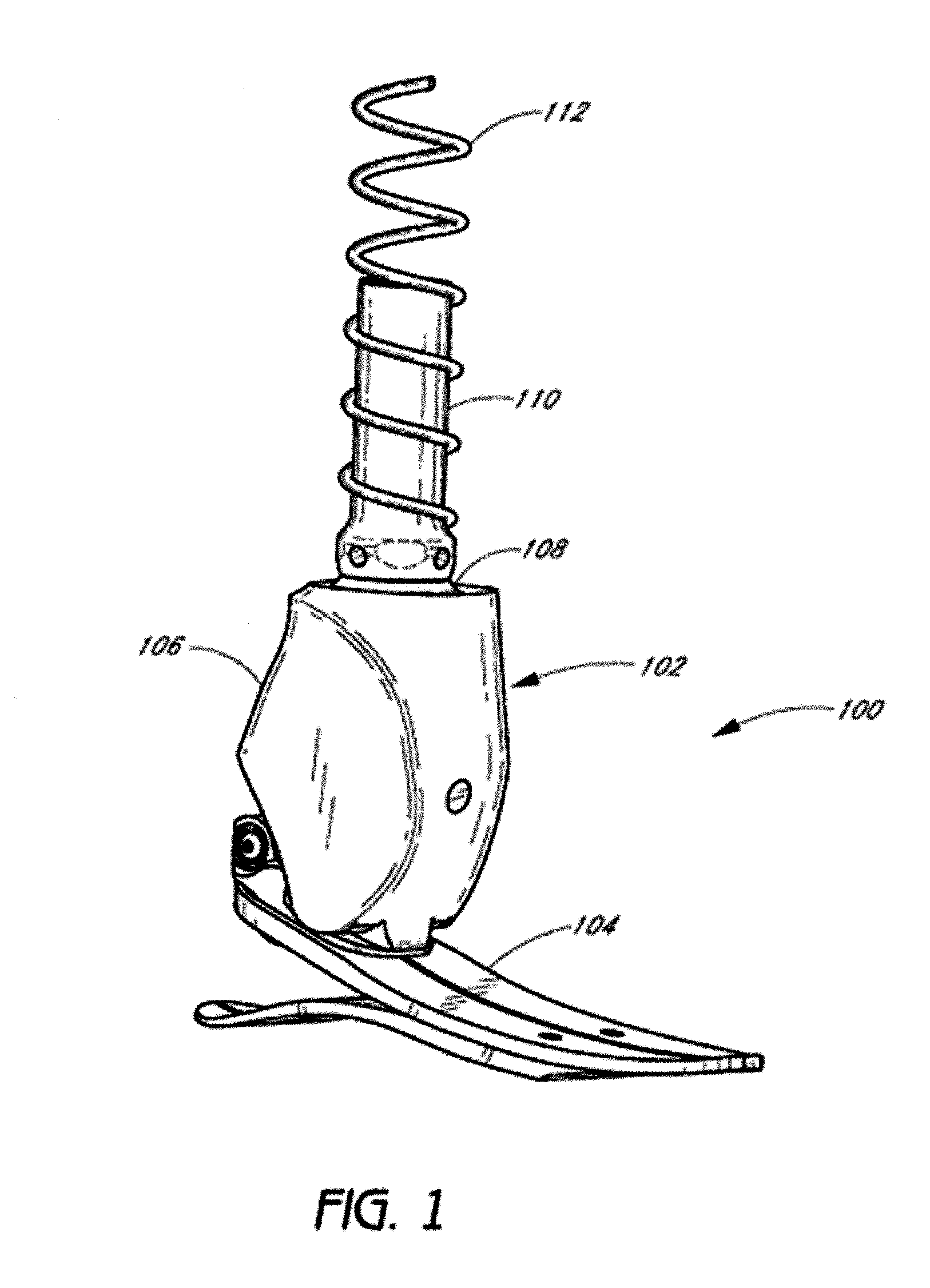
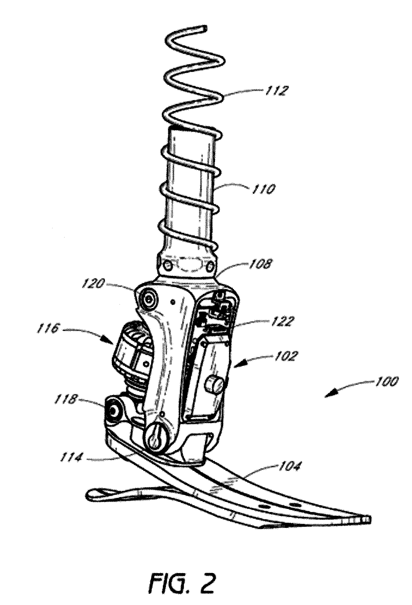
[0001] The present application is related to the following applications, each of which is incorporated herein by reference in its entirety and is to be considered a part of this specification: U.S. Application No. 11 / 056,344, filed February 11, 2005, and entitled “SYSTEM AND METHOD FOR MOTION-CONTROLLED FOOT UNIT”; U.S. Application No. 11 / 057,391, filed February 11, 2005, and entitled “SYSTEM AND METHOD FOR MOTION-CONTROLLED FOOT UNIT”; U.S. Provisional Application No. 60 / 544,259, filed February 12, 2004, and entitled “LOWER LIMB PROSTHESIS WITH ANKLE-MOTION-CONTROLLED FOOT”; and U.S. Provisional Application No. 60 / 588,232, filed July 15, 2004, and entitled “PROSTHETIC OR ORTHOTIC SYSTEM WITH ANKLE-MOTION-CONTROLLED FOOT.”
Background of the Invention
[0002] Field of the Invention
[0003] Preferred embodiments of this invention relate to systems and methods for controlling a prosthetic or orthotic joint, and in particular relates to a device and method for adjusting a...
PUM
 Abstract
Description
Claims
Application Information