Engine control system and engine control method

a control system and engine technology, applied in the direction of electric control, speed sensing governors, instruments, etc., can solve the problems of combustible components, deterioration of control accuracy of engine output, and difficulty in detecting the quantity of combustible components in intake air resulting from combustible components, so as to avoid lubrication defects and overrunning of engines, simple and effective manner

Inactive Publication Date: 2007-07-05
DENSO CORP
View PDF11 Cites 39 Cited by
  • Summary
  • Abstract
  • Description
  • Claims
  • Application Information

AI Technical Summary

Benefits of technology

[0109] Under such a condition, since the judging section makes judgment whether or not the mixing ratio of combustible components and the temperature of engine oil belong to an engine performance upgrading zone and providing an output if judgment is made that the mixing ratio of combustible components and the temperature of engine oil belong to the engine performance upgrading zone. The electronic control unit controls the fuel injection valve in response to the output to suppress an increase of the combustible components mixed to the engine oil. Thus, various measures can be taken to preliminarily avoid the lubrication defect and overrunning of the engine in a simple and effective manner.

Problems solved by technology

As such fuel components increase in intake air drawn to a combustion chamber of the engine, these fuel components results in an increase in a total volume of fuel in an air / fuel mixture to be prepared in the combustion chamber and, thus, the air / fuel mixture becomes too rich, causing a deterioration in control accuracy of an output of the engine.
With such a control device, however, it is hard to detect a combustible component quantity of intake air resulting from combustible components contained in blow-by gas ejected from the crankcase.
In addition, the presence of the combustible components causes a dilution of engine oil in the crankcase, resulting in a lubrication defect between a cylinder wall surface of the engine and a piston.

Method used


Image

  • Engine control system and engine control method
  • Engine control system and engine control method
  • Engine control system and engine control method

Examples


first embodiment

[0133] Now, an engine control system of a first embodiment according to the present invention applied to a diesel engine is described below in detail with reference to FIGS. 1 to 6C of the accompanying drawings.

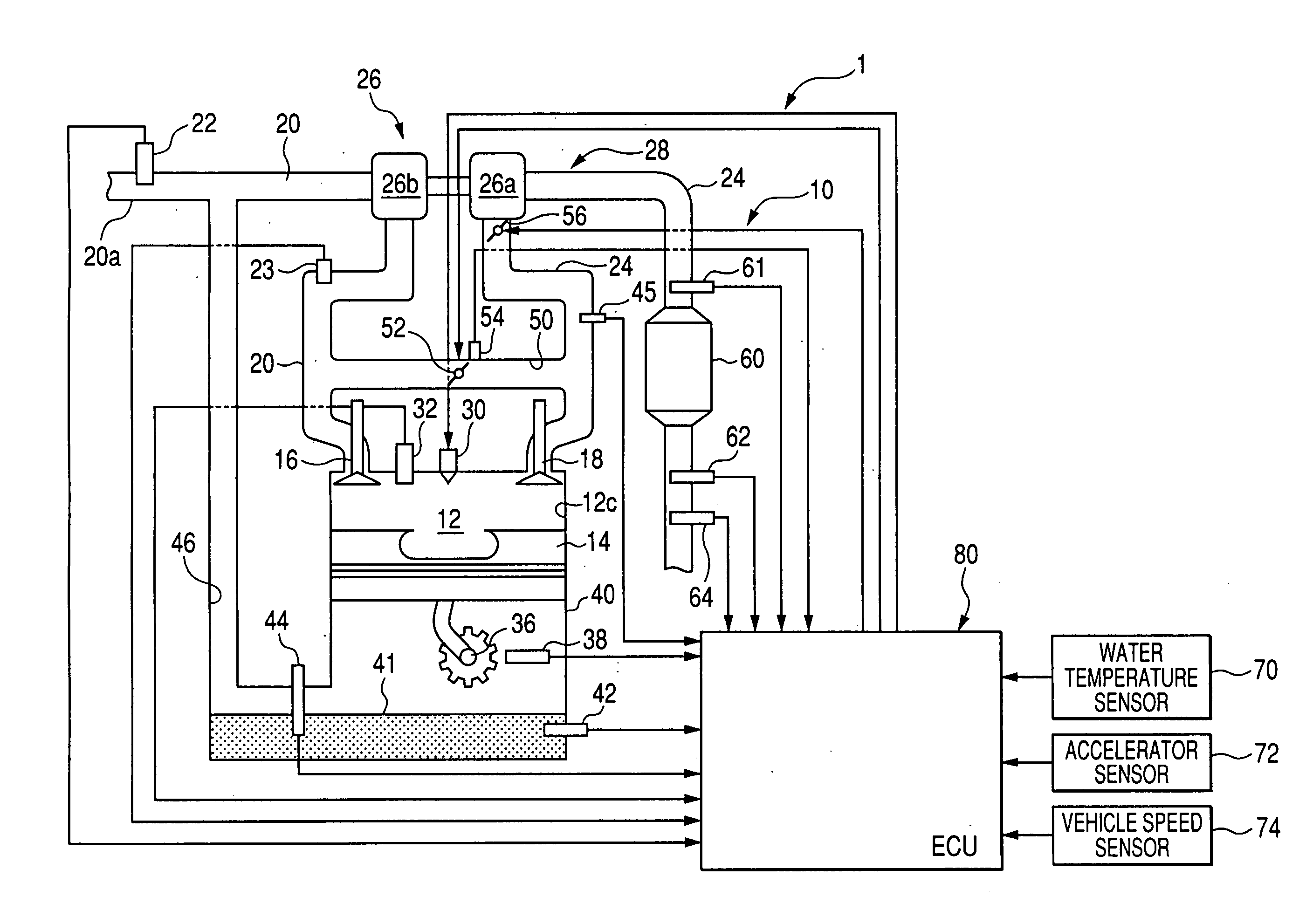
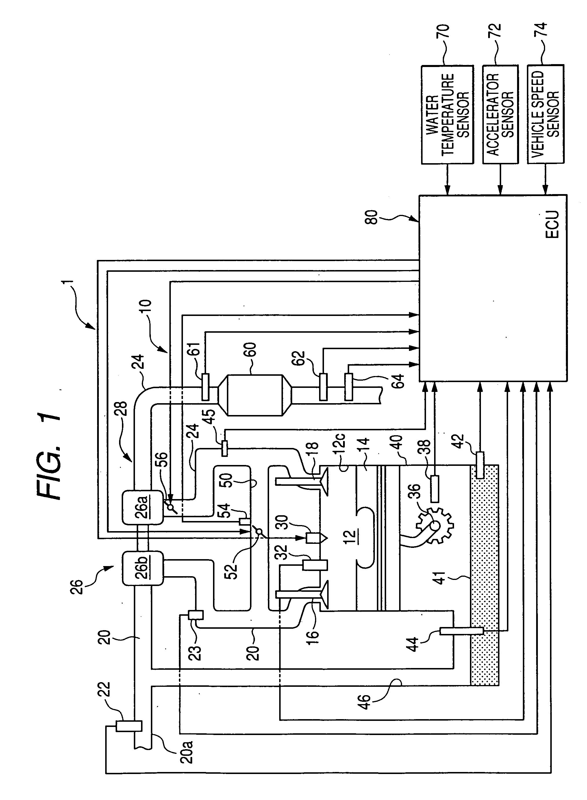
[0134]FIG. 1 is a block diagram showing an overall structure of the engine control system common to the first embodiment to a tenth embodiment. Thus, the engine control systems of the first to tenth embodiments are described below with reference to the overall structure of the engine control system shown in FIG. 1.

[0135] As shown in FIG. 1, a diesel engine 10 comprises a combustion chamber 12 in which a piston 14 is slidably disposed. The combustion chamber 12 has an intake port 12a and an exhaust port 12b in which an intake valve 16 and an exhaust valve 18 are operatively disposed, respectively. The intake port 10a is connected to an intake air passage 20 acting as an intake air system, supplying intake air to the combustion chamber 12, which has an upstream 20a on which a...

second embodiment

[0206] An engine control system of a second embodiment according to the present invention is described below in detail with reference to FIGS. 1, 2 and 7. The engine control system of the second embodiment differ from that of the first embodiment in that the CPU 84 is programmed to calculate a combustible component quantity of intake air in further increased accuracy on the basis of a learning value in a manner described below in detail.

[0207] With the first embodiment, the CPU 84 has been programmed to execute the operations for calculating the combustible component quantity of intake air, reflecting the combustible components contained in engine oil 41 inside the crankcase 40, on the basis of the deviation between the basic injection quantity and the actually commanded fuel injection quantity during the operation in idling stabilizing control.

[0208] However, a univocal determination of the combustible component quantity of intake air on the basis of the deviation between the bas...

third embodiment

[0219] An engine control system of a third embodiment according to the present invention is described below in detail with reference to FIGS. 1, 2, 8 and 9. With the third embodiment, the engine control system takes the form of the same structure as that of the first embodiment except for several features and the present embodiment is described below with reference to the diesel engine 10 shown in FIGS. 1 and 2 with a focus on such several features.

[0220] With the engine control system of the third embodiment, the CPU 84 is programmed to execute a basic sequence of operations, shown in FIG. 8, for calculating a combustible component quantity of intake air reflecting the combustible components prevailing in the crankcase 40. That is, the CPU 84 is programmed to repeatedly execute such operations for a given cycle.

[0221] In addition, the same steps as those shown in FIG. 3 bear like reference numerals in FIG. 8 for the sake of convenience.

[0222] Before entering into a detailed desc...


PUM


Abstract

An engine control system and an engine control method are disclosed wherein a combustible component quantity of intake air, reflecting combustible components in a crankcase of an engine, is calculated on the basis of a deviation between basic injection quantity for a target rotational speed to be attained and an actual injection quantity during operation to perform idling stabilizing control. A ratio of the combustible components mixed to engine oil is calculated on the basis of the combustible component quantity of intake air and a temperature of engine oil. During a status of the engine with a given temperature of engine oil and the mixing ratio of the combustible components in engine oil, a fuel injection affect eliminating operation is executed.

Description

CROSS REFERENCE TO RELATED APPLICATIONS [0001] This application is related to Japanese Patent Application No. 2005-369983, filed on Dec. 22, 2005, the content of which is hereby incorporated by reference. BACKGROUND OF THE INVENTION [0002] 1. Technical Field of the Invention [0003] The present invention relates to engine control devices for controlling internal combustion engines and, more particularly, to an engine control system and an engine control method having a function to detect or calculate a combustible component quantity of intake air of an internal combustion engine. [0004] 2. Description of the Related Art [0005] In the related art, attempts have heretofore been made to provide an internal combustion engine having a combustion chamber supplied with intake air containing fresh air and fuel components such as evaporative fuel delivered from a fuel tank or blow-by gas ejecting from a crankcase. As such fuel components increase in intake air drawn to a combustion chamber of...

Claims


Application Information

Patent Timeline
Patent Type & Authority Applications(United States)
IPC IPC(8): G06F19/00F02B25/06F02D41/14F02D21/08F02D41/02F02D41/04F02D41/38F02D45/00F02M25/07
CPCF02D41/0072F02D41/123F02D41/1446F02D41/16F02D2200/023F02D41/2467F02D41/405F02D2041/227F02D41/22
Inventor SOGA, TSUTOMUKOJIMA, KAZUO
Owner DENSO CORP
Why Eureka
Try Eureka