
Configurations and methods of integrated NGL recovery and LNG liquefaction

Inactive Publication Date: 2007-07-12
FLUOR TECH CORP
View PDF7 Cites 71 Cited by
  • Summary
  • Abstract
  • Description
  • Claims
  • Application Information

AI Technical Summary

Benefits of technology

[0010] The present invention is directed to configurations, plants, and methods for natural gas processing and liquefaction in which a cold separator overhead product is directly compressed in a compressor that is driven by a feed gas vapor expander, and wherein the compressed cold separator overhead product is then liquefied in a liquefaction unit. Most advantageously, such plants integrate NGL processing and LNG liquefaction in an efficient, cost effective, and technically simple manner.

Problems solved by technology

However, in remote locations lacking the necessary pipeline infrastructure, natural gas is commonly transported by liquefying the natural gas and transporting the gas in liquid form (e.g., using LNG cargo carriers).
Unfortunately, liquefaction of natural gas is problematic as natural gas also contains aromatics (e.g., benzene) and heavy hydrocarbons, which solidify when chilled to the cryogenic temperatures.
While these processes improve C2 recovery to at least some degree, the energy spent for residue gas recompression renders the process often uneconomical.
However, as these NGL processes operate independently from the liquefaction plants, they will generally require additional compression and refrigeration prior to LNG liquefaction of the residue gas.
While such process can advantageously be used to eliminate wax formation by removal of C6+ and heavier components, they are not suitable for the removal of C2+ components, especially at high levels (65% or higher C2 recovery) and consequently fail to produce the lean residue gas that can be liquefied for the North American natural gas market.
While such processes attempt to operate the absorption column at high feed gas pressure (e.g., 800 psig or higher) to reduce energy consumption, it should be noted that NGL separation suffers significantly due to decreasing relative volatilities of the NGL components, consequently producing NGL with excessive methane content.
Moreover, such process schemes typically fail to achieve high C2 and C3 recovery (e.g., greater than 60%).
Unfortunately, most known standalone LNG liquefaction processes using single or multiple refrigeration cycles (either cascade refrigeration or mixed refrigerant cycle) have relatively low efficiencies when C2 or C3 recovery is incorporated upstream of the LNG liquefaction plant.
Thus, while numerous plant configurations and methods for NGL recovery and LNG liquefaction are known in the art, all or almost all of them, suffer from various disadvantages.

Method used


Image

  • Configurations and methods of integrated NGL recovery and LNG liquefaction
  • Configurations and methods of integrated NGL recovery and LNG liquefaction
  • Configurations and methods of integrated NGL recovery and LNG liquefaction

Examples


Embodiment Construction

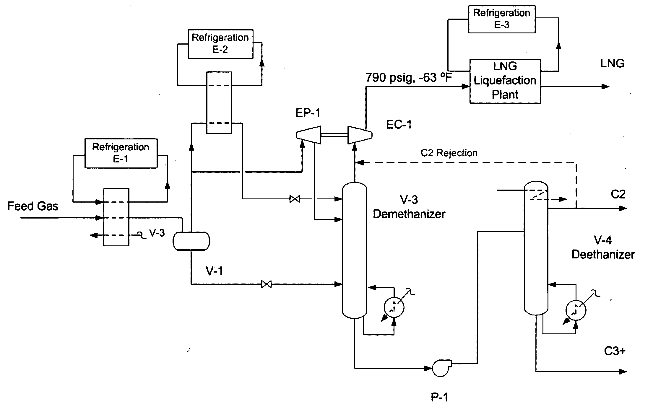
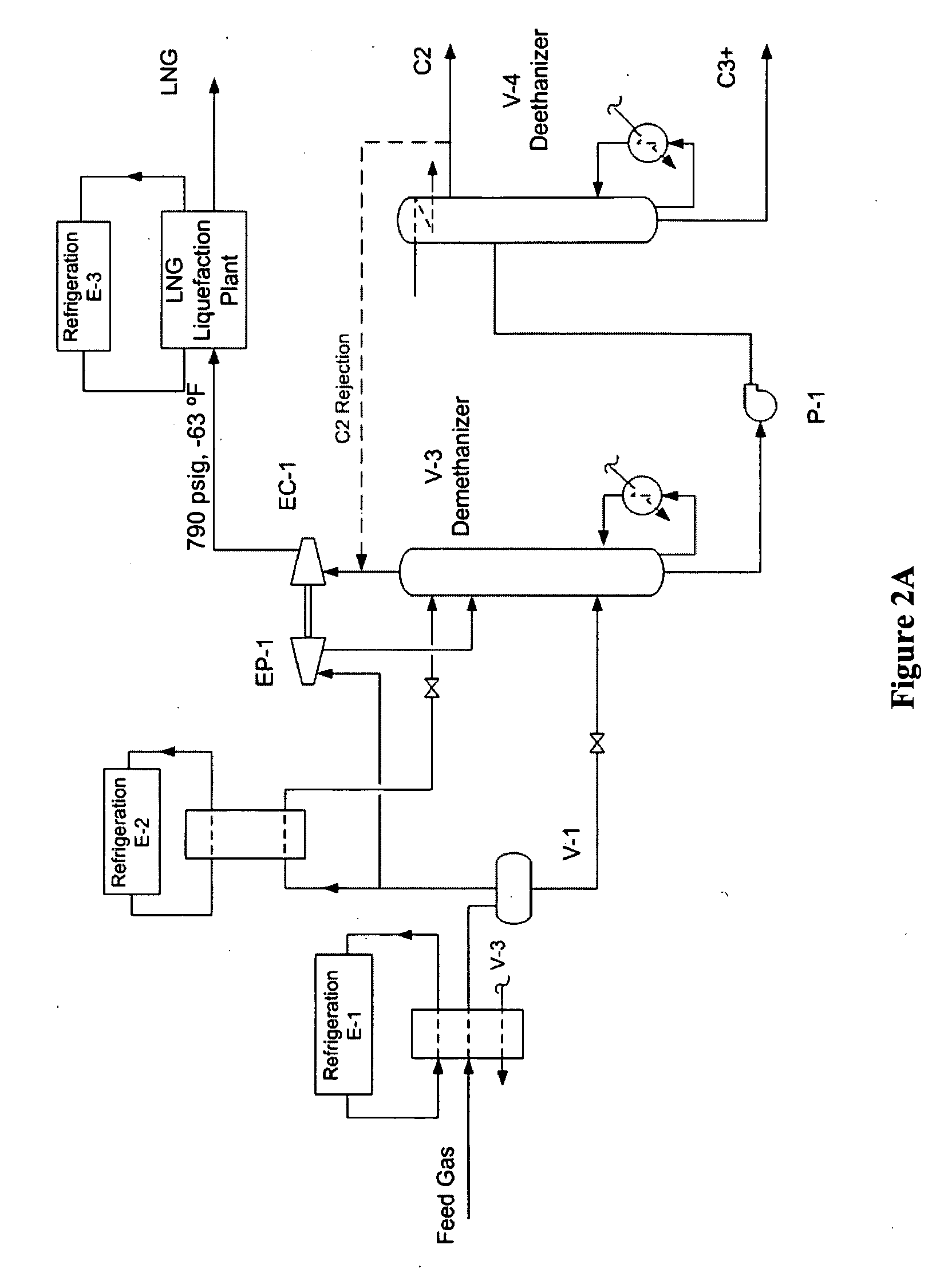
[0026] The inventor discovered that natural gas processing and liquefaction can be integrated in various configurations, plants, and methods in which cold compression of lean natural gas in a compressor that is driven by a feed gas expander provides a cold high-pressure natural gas that can be directly liquefied in a liquefaction unit. Therefore, the net compression energy requirement for the lean natural gas is neutral or even negative, while feed gas cooling and condensation are achieved using distinct refrigeration cycles. Among other advantages, it should be appreciated that contemplated configurations and methods allow for an integrated NGL recovery and LNG liquefaction process in which 99% propane and up to 85% ethane can be recovered from a natural feed gas.

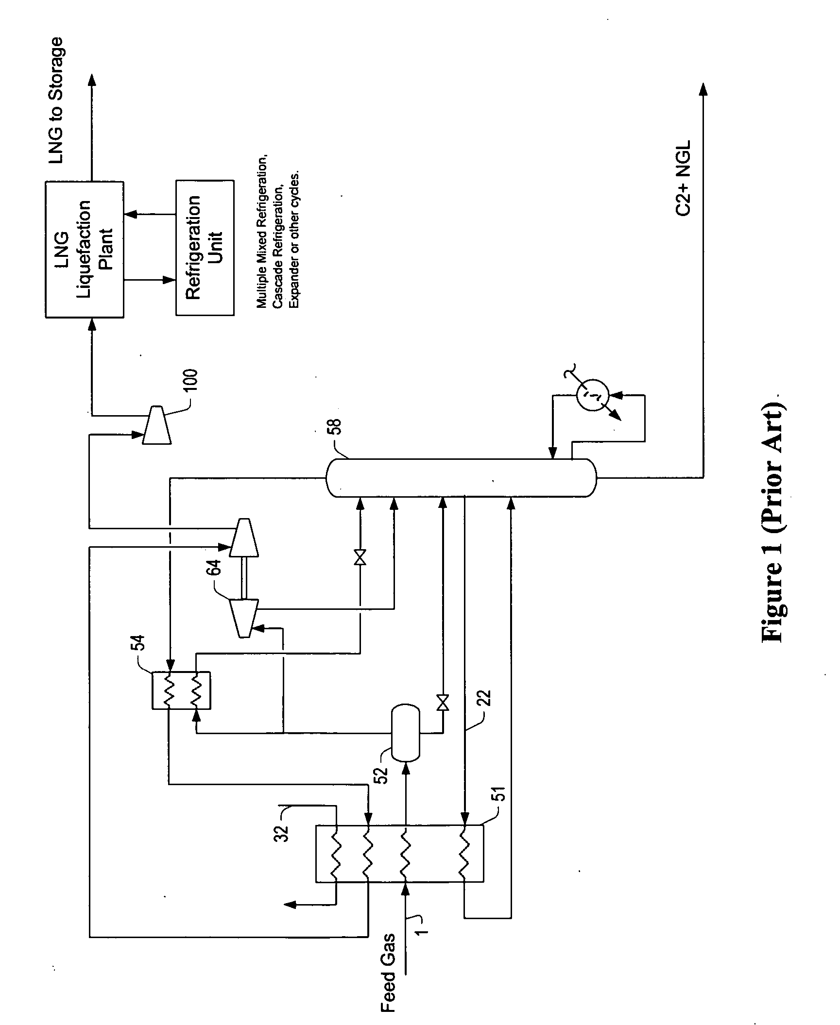
[0027] Prior Art FIG. 1 shows a standalone C2 NGL recovery process that is coupled with a standalone LNG liquefaction plant. Here, a contaminant free and dried feed gas stream 1, typically supplied at about 1200 psig is c...


PUM


Abstract

Contemplated plants include a NGL recovery portion and a LNG liquefaction portion, wherein the NGL recovery portion provides a low-temperature and high-pressure overhead product directly to the LNG liquefaction portion. Feed gas cooling and condensation are most preferably performed using refrigeration cycles that employ refrigerants other than the demethanizer / absorber overhead product. Thus, cold demethanizer / absorber overhead product is compressed with the turbo-expansion and delivered to a liquefaction portion at significantly lower temperature and higher pressure without net compression energy expenditure.

Description

[0001] This application claims priority to our copending U.S. provisional patent application with the Ser. No. 60 / 697,467, which was filed 7 Jul. 2005.FIELD OF THE INVENTION [0002] The field of the invention is natural gas liquids (NGL) recovery and liquefied natural gas (LNG) liquefaction, and particularly integrated plant configurations for such processes. BACKGROUND OF THE INVENTION [0003] While the crude oil supply in the world is diminishing, the supply of natural gas is still relatively abundant in many parts of the world. Natural gas is typically recovered from oil and gas production wells located onshore and offshore. Depending on the particular formation and reservoir, natural gas also contains relatively low quantities of non-methane hydrocarbons, including ethane, propane, i-butane, n-butane, pentanes, hexane and heavier components, as well as water, nitrogen, carbon dioxide, hydrogen sulfide, mercaptans, and other gases. [0004] Natural gas from the wellheads is commonly ...

Claims


Application Information

Patent Timeline
IPC IPC(8): F25J1/00F25J3/00
CPCF25J1/0022F25J2270/66F25J1/0045F25J1/0052F25J1/0207F25J1/0218F25J1/0231F25J1/0239F25J1/0291F25J1/0292F25J3/0209F25J3/0233F25J3/0238F25J3/0242F25J2200/02F25J2200/04F25J2200/70F25J2200/72F25J2200/78F25J2205/04F25J2215/02F25J2215/62F25J2220/62F25J2230/08F25J2230/60F25J2240/02F25J2245/02F25J2270/02F25J2270/12F25J2270/60F25J1/0035
Inventor MAK, JOHNGRAHAM, CURT
Owner FLUOR TECH CORP
Features
  • Generate Ideas
  • Intellectual Property
  • Life Sciences
  • Materials
  • Tech Scout
  • Unparalleled Data Quality
  • Higher Quality Content
  • 60% Fewer Hallucinations
Learn More