Hospital bed

a technology for supporting equipment and beds, applied in the field of hospital beds, can solve the problems of unsafe bed movement, large patient weight, and inability to meet the needs of emergency situations, and achieve the effects of increasing the speed of the actuator, and increasing the speed of the movemen

Active Publication Date: 2007-07-19
STRYKER CORP
View PDF49 Cites 146 Cited by
  • Summary
  • Abstract
  • Description
  • Claims
  • Application Information

AI Technical Summary

Benefits of technology

[0032] In another aspect, control system increases the voltage to the actuator to thereby increase the speed of the actuator. Further, the control system may be adapted to couple to a remote power supply, which has a voltage, with the control system converting the voltage supplied by the remote power supply to deliver a first voltage to the actuator. Further, the control system converts the voltage of the remote power supply to a second voltage to deliver a second voltage to the actuator wherein the second voltage is greater than the first voltage to increase the speed of the actuator and thereby increase the speed of the movement of the head-end section.
[0033] In another aspect, the bed includes a battery. The control system is adapted to couple to a remote power supply and is adapted to convert the voltage of the remote power supply into a first voltage and to deliver the first voltage to the actuator. Further, the control system uses the voltage of the battery to increase the first voltage to the actuator. For example, the control system delivers about 12 volts to the actuator and selectively increases the voltage to the actuator from about 12 volts to about 24 volts to thereby increase the speed of the head-end section.

Problems solved by technology

There are certain disadvantages associated with such foot brakes.
In addition, if the patient is exiting the bed, the bed may move which is unsafe.
Furthermore, the weight of present day beds and patients are relatively large, requiring sufficient braking force to hold a bed in a desired location in a hospital.
The manual- or motor-driven mechanism utilized to raise and lower the Fowler section typically moves too slowly to be acceptable in an emergency situation.
Accordingly, emergency releases have been developed to quickly disengage the Fowler section from the drive mechanism to allow for rapid movement, however, these arrangements can be complex, bulky, expensive and difficult to engage and disengage.
Movement of the foot-end of a hospital bed to various positions that are not aligned with the remainder of the bed, such as a chair position, is difficult when it forms part of the main bed frame
Such manual systems suffer from the need for considerable physical effort to adjust the bed height.
Such hydraulic systems are known to be relatively expensive and prone to leakage.
Additionally, prior mechanical systems suffer from excessive complexity, excessive size, a lack of load capacity, and manufacturing difficulties.
Hospital bed side rails of the prior art comprise support arms which form undesirable pinch points for users.
The movement of such side rails from the deployed to the stowed positions is often hampered by side rail oscillations.
The side rail falls due to gravity and the movement can jar the bed and disturb patients.
This is problematic in circumstances where the life of the battery itself has run out or in settings where a suitable power supply to recharge the battery is not available.
If the bed is in a confined space, such as a narrow corridor or elevator, this action may be difficult to execute and result in an undesirable delay in effecting the change in position of the patient.
This technique, however, suffers from the drawback that any misalignment in the frame of reference severely affects the integrity of the sensed angular position.
Although the accelerometers can provide an effective way to measure the inclination in the patient's position, the resolution of the gravitational accelerometers is restricted to a limited range of inclination angles.
Since footboards were not designed to support the hanging of pumps (or other hospital equipment), this current practice reduces access to the controls on footboards, damages foot controls and footboards, generates bed motions and causes damage to pumps (and other equipment) that fall from its hangers.
Ordinarily, there is a tendency for detached headboards or footboards placed in an upright position against an object or structure to slip, thereby causing the headboard or footboard to fall and potentially suffer damage.
In a busy hospital, a discarded headboard or footboard that has fallen to the floor creates a tripping hazard to both staff, who may be carrying equipment or medication and thus have an obstructed view of the floor, and patients, who may have compromised mobility owing to illness.
Preventing slippage, therefore, reduces the likelihood of personal injury stemming from hastily removed headboards and footboards.
Existing motorized hospital beds utilize a single speed or multiple defined and preprogrammed speeds for bed movement resulting in the user having to manually switch speeds.
Variable speeds in these beds are not automatic

Method used


Image

  • Hospital bed
  • Hospital bed
  • Hospital bed

Examples


Embodiment Construction

[0156] The bed of the present invention comprises structural elements (Section I), power and control systems (Section II); structural informatics systems (Section III); user-bed communication interfaces (Section IV); and bed-network communications systems (Section V).

[0157] Unless defined otherwise, all technical and scientific terms used herein have the same meaning as commonly understood by one of ordinary skill in the art to which this invention pertains.

I. Structural Elements

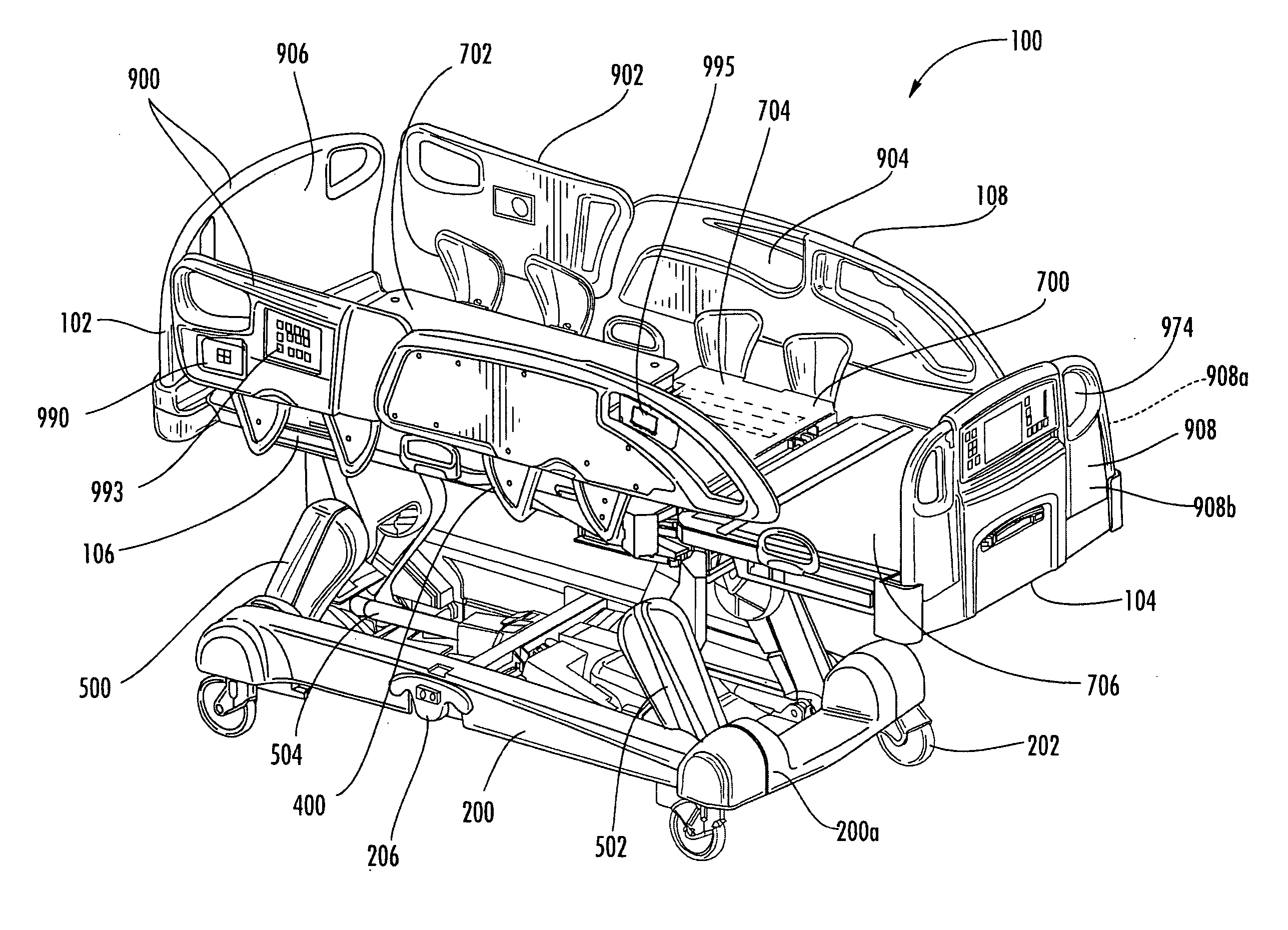
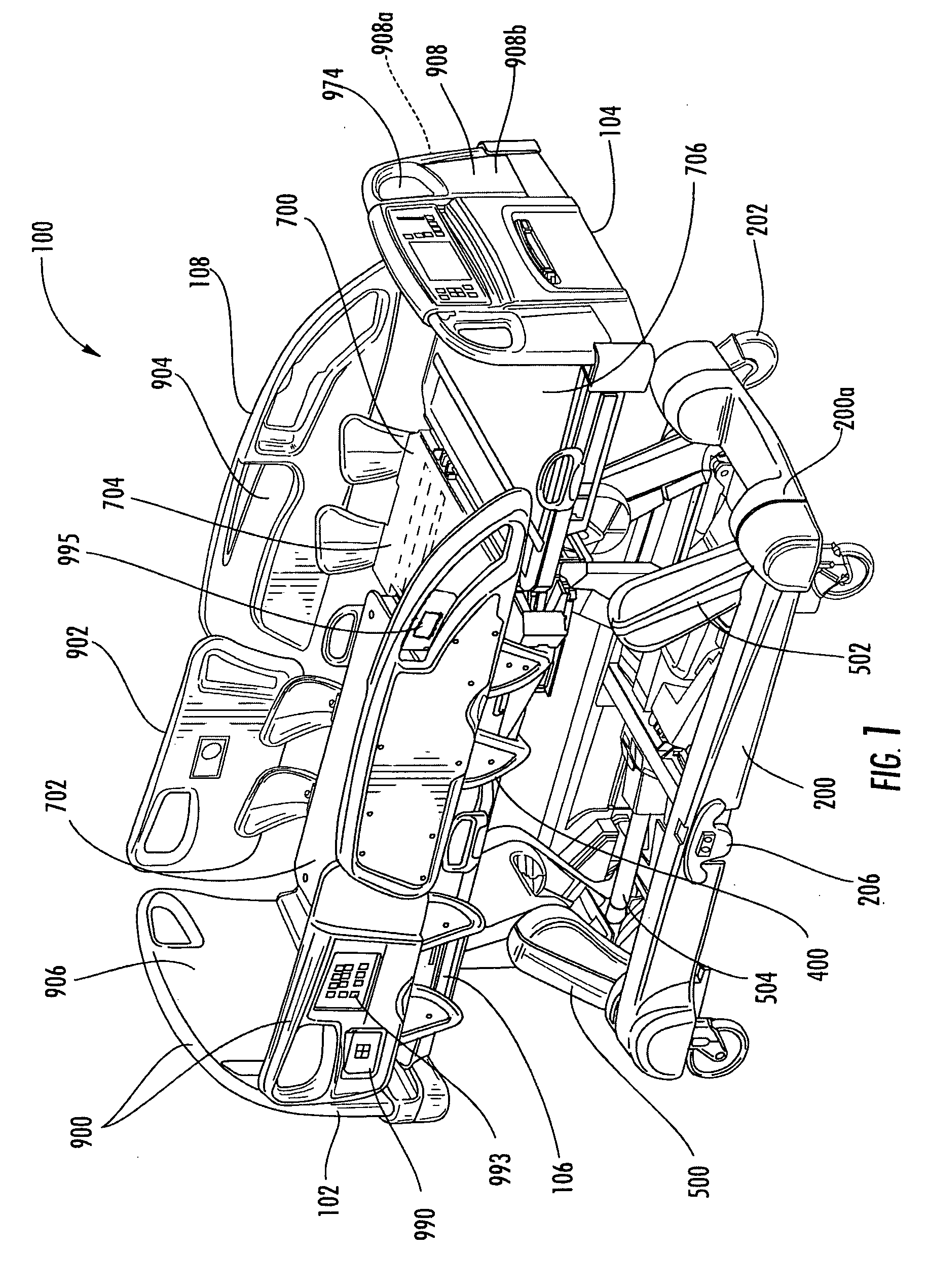
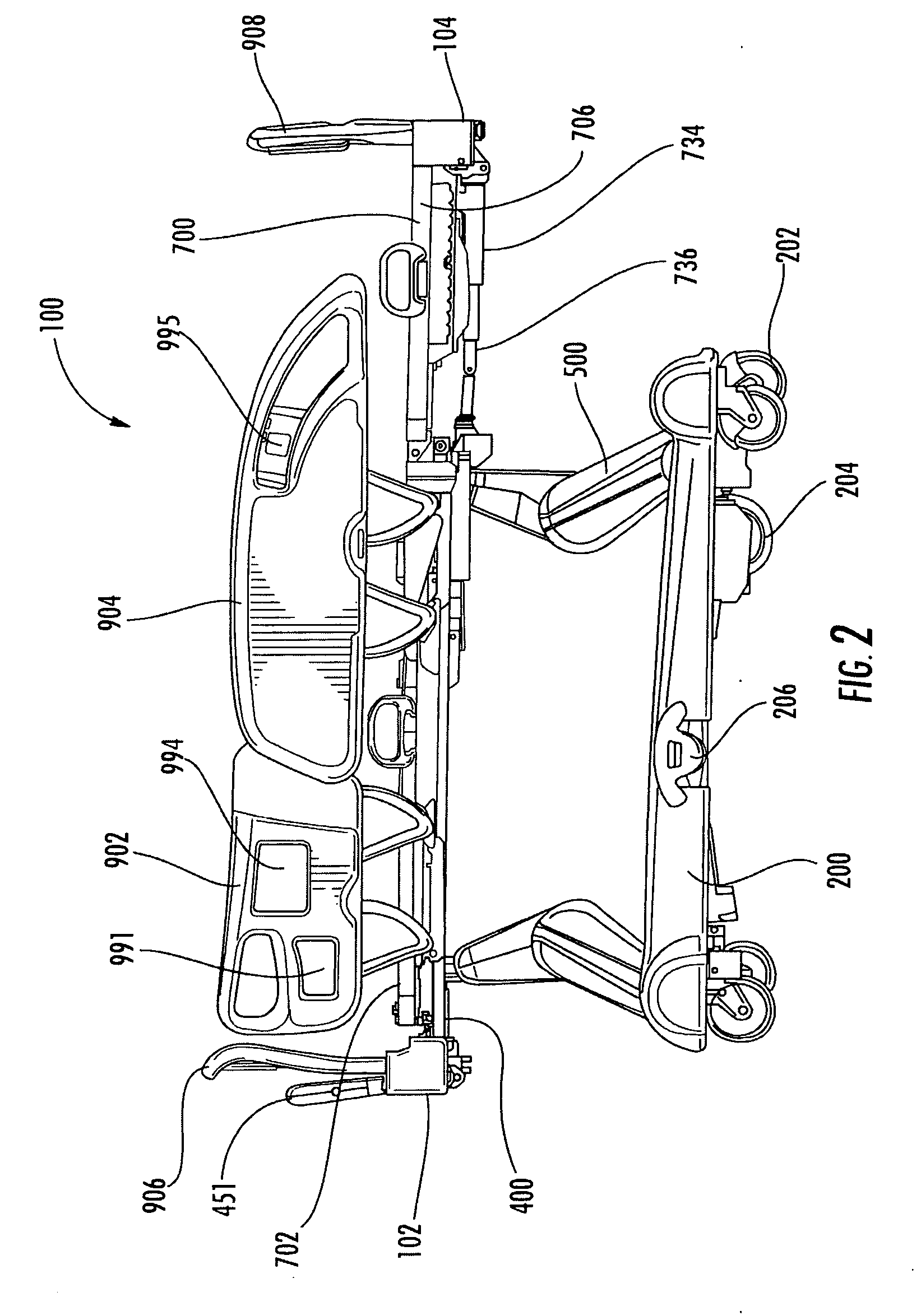
[0158] A hospital bed, generally referred to using the numeral 100 and in accordance with an embodiment of the present invention, is generally shown in FIGS. 1 to 8. For the purpose of this description, the bed 100 may be defined to include a head-end 102 and an opposing foot-end 104, respectively defining the ends of the bed 100 at which a user's head and feet may be positioned, and right and left sides 106 and 108 joining these ends.

[0159] The bed 100 generally includes a frame system that forms a pat...


PUM


Abstract

A patient bed includes a base, a patient support, and an elevation mechanism for raising or lowering the patient support relative to the base. The elevation mechanism comprises a first pair of arms and a second pair of arms, with both the pairs of arms mounted relative to the patient support and the base. The first pair of arms and the second pair of arms have pivot connections at the patient support, with the pivot connections of at least one pair of the pair of arms moving in a sinusoidal path when the patient support is raised or lowered with respect to the base.

Description

CROSS-REFERENCE TO RELATED APPLICATIONS [0001] This application claims priority from U.S. provisional application Ser. No. 60 / ______, filed Dec. 11, 2006, entitled HOSPITAL BED, by Applicant Guy Lemire, and U.S. provisional application Ser. No. 60 / 751,770, filed Dec. 19, 2005, entitled HOSPITAL BED, by Applicant Guy Lemire, which are incorporated by reference herein in their entireties.FIELD OF THE INVENTION [0002] The present invention relates in general to the field of patient support apparatuses such as hospital beds. In particular, the invention relates to critical care patient support apparatuses with improved safety features, expanded configurability and accessible control and electronics for users. BACKGROUND OF THE INVENTION [0003] Hospital beds comprise complex mechanical and electronic components for movement, functionality and convenience. [0004] Foot brakes of prior art hospital beds are typically located on the side under the bed. There are certain disadvantages associa...

Claims


Application Information

Patent Timeline
Patent Type & Authority Applications(United States)
IPC IPC(8): A61G7/015A61G7/05
CPCA61G7/005A61G7/0506A61G7/015A61G7/018A61G7/05A61G7/0507A61G7/08A61G2007/0509A61G2007/0514A61G2007/052A61G2007/0524A61G2007/0527A61G2007/0528A61G2203/16A61G2203/20A61G2203/32A61G2210/50G06F19/3406A61G2203/36A61G2203/42A61G2203/44A61G2203/46B60T7/085B60T17/22A61G7/012A61G7/0509A61G7/0514A61G7/052A61G7/0524A61G7/0527A61G7/0528A61M5/1415G16H40/63A61G7/1046A61G7/0516
Inventor LEMIRE, GUYMORIN, MARCOPARE, RICHARD
Owner STRYKER CORP
Why Eureka
Try Eureka